
"The Laws of Voltage in Series and Parallel Circuits" Voltage Resistance PPT Teaching Courseware Simple campus recruitment activity planning plan summary enterprise and institution recruitment publicity lecture PPT template is a general PPT template for business post competition provided by the manuscript PPT, simple campus recruitment activity planning plan summary enterprise and institution recruitment promotion Lecture PPT template, you can edit and modify the text and pictures in the source file by downloading the source file. If you want more exquisite business PPT templates, you can come to grid resource. Doug resource PPT, massive PPT template slide material download, we only make high-quality PPT templates!
| 文件名 如何下载使用 | 下载次数 | Download Points | 下载地址 |
|---|---|---|---|
| "The Laws of Voltage in... | 3525次 | 0.00 | Free Download |
Tips: If you open the template and feel that it is not suitable for all your needs, you can search for related content "The Laws of Voltage in Series and Parallel Circuits" Voltage Resistance PPT Teaching Courseware is enough.
How to use the Windows system template
Directly decompress the file and use it with office or wps
How to use the Mac system template
Directly decompress the file and use it Office or wps can be used
Related reading
For more detailed PPT-related tutorials and font tutorials, you can view: Click to see
How to create a high-quality technological sense PPT? 4 ways to share the bottom of the box
Notice
Do not download in WeChat, Zhihu, QQ, built-in browsers, please use mobile browsers to download! If you are a mobile phone user, please download it on your computer!
1. The manuscript PPT is only for study and reference, please delete it 24 hours after downloading.
2. If the resource involves your legitimate rights and interests, delete it immediately.
3. Contact information: service@daogebangong.com
"The Laws of Voltage in Series and Parallel Circuits" Voltage Resistance PPT Teaching Courseware, due to usage restrictions, it is only for personal study and reference use. For commercial use, please go to the relevant official website for authorization.
(Personal non-commercial use refers to the use of this font to complete the display of personal works, including but not limited to the design of personal papers, resumes, etc.)
Related reading
For more detailed PPT-related tutorials and font tutorials, you can view:Please click to see


Authoritative PPT Summary
"The Laws of Voltage in Series and Parallel Circuits" Voltage Resistance PPT Teaching Courseware
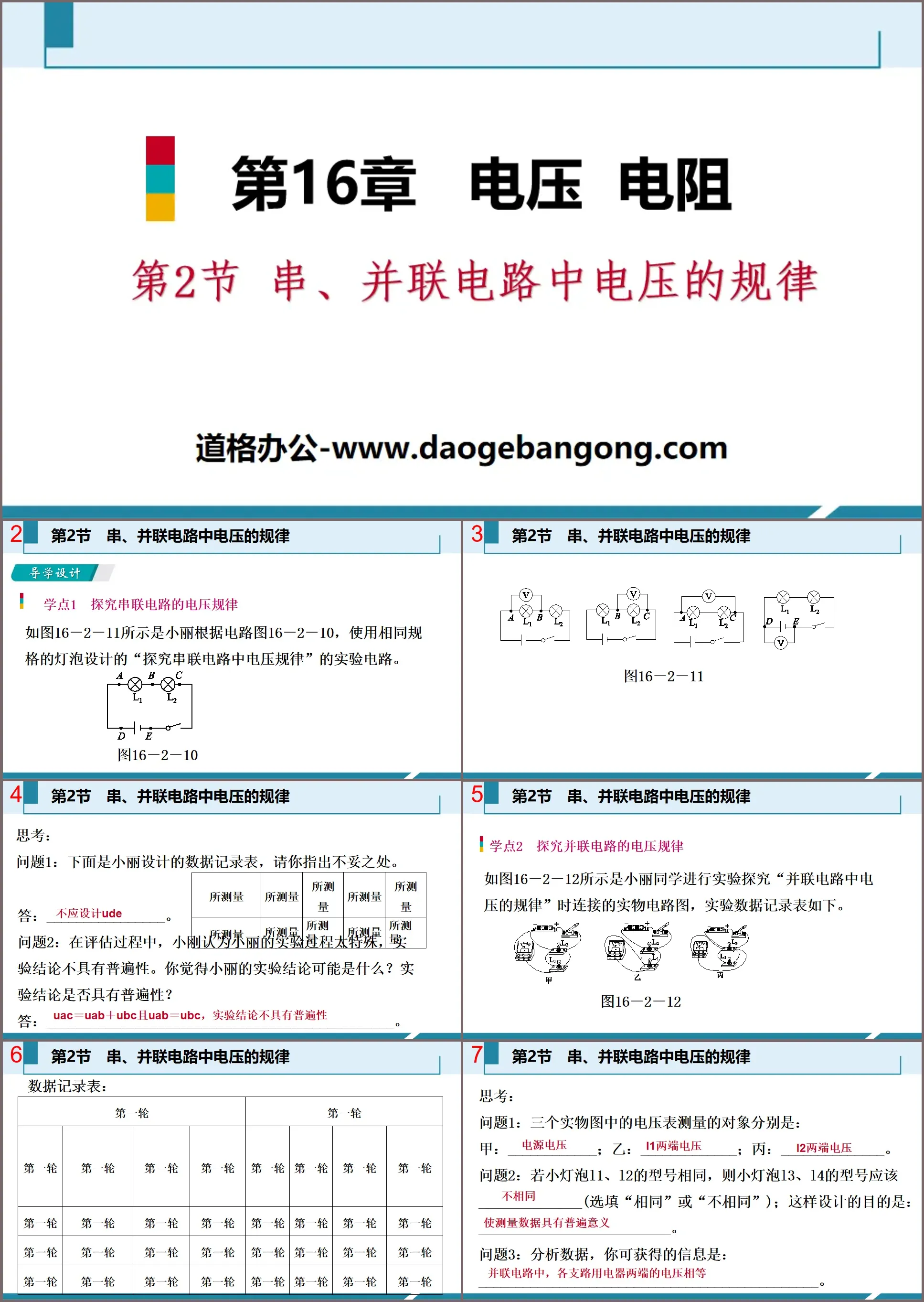
Part One: Guidance Design
Learning point 1: Explore the voltage laws of series circuits
As shown in Figure 16-2-11, Xiaoli designed an experimental circuit to "explore the voltage rules in series circuits" based on circuit diagram 16-2-10, using light bulbs of the same specifications.
think:
Question 1: The following is the data record table designed by Xiaoli. Please point out the inaccuracies.
answer:________________.
Question 2: During the evaluation process, Xiaogang believed that Xiaoli’s experimental process was too special and the experimental conclusions were not universal. What do you think the conclusion of Xiaoli’s experiment might be? Are the experimental conclusions universal?
Answer: UAC=UAB+UBC and UAB=UBC, the experimental conclusion is not universal.
Learning point 2: Explore the voltage rules of parallel circuits
Figure 16-2-12 shows the physical circuit diagram connected when Xiaoli conducted an experiment to explore the "law of voltage in parallel circuits". The experimental data record table is as follows.
think:
Question 1: The objects measured by the voltmeters in the three physical pictures are:
A: ____________; B: ____________; C: ______________.
Question 2: If the models of small light bulbs L1 and L2 are the same, the models of small light bulbs L3 and L4 should be ______________ (optional "same" or "not the same"); the purpose of this design is: ____________________________.
Question 3: Analyzing the data, the information you can obtain is: ____________________________________________.
The law of voltage in series and parallel circuits PPT, part 2: application examples
Type 1: Research on voltage rules of series and parallel circuits
Example 1 In the experiment of "Exploring the voltage rules of series and parallel circuits", Zhang Qiang connected the circuits according to the circuit diagrams A and B in Figure 16-2-2 and conducted the experiment. He recorded the measured data in Tables 1 and 2 respectively. Second middle school.
(1) Analyzing the data in Table 1 can lead to the conclusion: __________________________________________________; analyzing the data in Table 2 can lead to the conclusion: __________________________________________________.
(2) What comments and suggestions can you make about Zhang Qiang’s experimental process?
Your reason for making this suggestion is ______________________________________________________.
[Experimental Points] Grasp the experimental test points and answer the experimental inquiry questions correctly
(1) During the experiment, small bulbs of different specifications should be used for multiple experiments. The purpose is to avoid the contingency and particularity of the experimental data and make the conclusions obtained through the experiment more universal.
(2) When connecting the circuit, make sure the switch is turned off.
(3) The range of the voltmeter can be selected according to the power supply voltage used in the experiment. If the power supply voltage is unknown, use the touch-test method to select the appropriate range.
(4) When the switch is closed and the experiment is started, if the pointer of the voltmeter is found to deflect in the opposite direction, it means that the "+" and "-" terminals of the voltmeter are connected reversely; if the pointer of the voltmeter is found to move quickly to the rightmost side of the dial , indicating that the selected range is too small.
Type 2 Application of Voltage Laws in Series and Parallel Circuits
Example 2: In the circuit shown in Figure 16-2-3, when switch S is connected to a, the voltage indicated is 9 V. When switch S is connected to b, the voltage indicated is 4 V. Which of the following statements is incorrect ()
A. The supply voltage is 9 V
B. The voltage across lamp L1 is 4 V
C. The voltage across lamp L2 is 4 V
D. The total voltage of lamp L1 and lamp L2 is 9 V
[ Analysis V, the total voltage of lamp L1 and lamp L2 is 9 V, A and D are correct; when switch S is connected to b, the two bulbs are connected in series, and the voltmeter measures the voltage at both ends of L2, that is, the voltage at both ends of lamp L2 is U2 = 4 V , C is correct; the voltage across the lamp L1 is U1=U-U2=9 V-4 V=5 V, B is wrong. So choose B.
[Method Guidance]Application of Voltage Laws in Series Circuits
(1) When multiple electrical appliances are connected in series, the total voltage is equal to the sum of the voltages at both ends of each electrical appliance, so the series circuit has a voltage dividing effect.
(2) In a series circuit, the voltages assigned to each electrical appliance are not necessarily equal. When the electrical appliances connected in series have the same specifications, the voltages at both ends of them are equal.
Example 3 Figure 16-2-4 A is a circuit diagram for measuring the voltage of a small light bulb. After the switch is closed, the indications of the voltmeter V1 and V2 pointers are as shown in Figures B and C respectively. Then the voltages across the bulbs L1 and L2 are ( )
A. 0.5 V and 2.5 V
B. 0.5 V and 12.5 V
C. 2.5 V and 12.5 V
D. 2.5 V and 2.5 V
[ Analysis According to the equal voltage of each branch in the parallel circuit, the selected range of voltmeter V1 is 0~15 V, its graduation value is 0.5 V, and the reading is 2.5 V, that is, the voltage at both ends of bulb L1 is 2.5 V; voltmeter V2 The selected measuring range is 0~3 V, its graduation value is 0.1 V, and the reading is 2.5 V, that is, the voltage across the bulb L2 is 2.5 V.
[Method Guidance]Application of Voltage Laws in Parallel Circuits
(1) In a circuit in which dual-purpose electrical appliances are connected in parallel, the voltages at both ends of each branch are equal and equal to the power supply voltage.
(2) When multiple electrical appliances are connected in parallel, the voltages at both ends of each branch are still equal. As long as the voltage across a certain branch or the power supply voltage is known, the voltage across other branches can be inferred.
Type 3: Determine circuit fault based on the voltmeter indication
Example 4 is shown in Figure 16-2-5. After the switch S is closed, neither L1 nor L2 emits light. When the voltmeter is connected in parallel between ab, the voltage indication number is 0. When the voltmeter is connected in parallel between bc, The voltage indicates a large number. If there is only one fault in the circuit, the fault may be ()
A. L2 open circuit B. L2 short circuit
C. L1 open circuit D. L1 short circuit
[Analysis] After switch S is closed, both L1 and L2 do not light up, indicating that there is a break in the circuit. When the voltmeter is connected in parallel between ab, the voltage indication number is 0, indicating that the circuit other than the parallel circuit with the voltmeter is broken; when the voltmeter is connected in parallel between bc, the voltage indication number is larger, indicating that the circuit connected in parallel with the voltmeter The circuit is open, that is, L1 is intact and L2 is open. Therefore option A is correct.
[Method Guidance]Methods to determine circuit faults based on voltage indications
When conducting experimental research or using a voltmeter to detect whether there is a fault in a certain circuit, the voltmeter needs to be connected in parallel with the circuit being measured. The circuit fault can be analyzed and judged based on the indication of the voltmeter, as follows:
(1) If the voltmeter shows a number, it means that there is current flowing through the voltmeter or the two terminals of the voltmeter are connected to the two poles of the power supply. If there is a break in the circuit, the break must be in parallel with the voltmeter. On the circuit part, at this time the voltage indicated number is close to the power supply voltage.
(2) If the voltmeter has no indication, it means that there is no current flowing through the voltmeter. Possible reasons are: ① The terminals of the voltmeter are in poor contact; ② The circuit under test is short-circuited; ③ There is an open circuit outside the circuit under test.
PPT on the law of voltage in series and parallel circuits, part 3: classroom feedback
1. Xiao Ming conducted an experiment to “explore the voltage patterns of series and parallel circuits” based on the circuit shown in Figure 13-1, and recorded the experimental data in the table below.
(1) Analysis shows that: the experimental records shown in Table 1 are consistent with the figure ________ (please fill in "A" or "B"); the experimental records shown in Table 2 are consistent with the figure ________ (please fill in "A" or "B") ") consistent.
(2) From the analysis of experimental data in Table 1, it can be seen that: _______________________________________________.
(3) From the analysis of experimental data in Table 2, it can be seen that: __________________________________________________.
(4) Please give your opinion on Xiao Ming’s experiment: _______________________________________.
2. In the circuit shown in Figure 13-2A, when switch S is closed, the readings of voltmeter V and V1 are as shown in Figures B and C respectively, then the power supply voltage is ______V, and the reading of voltmeter V1 is ________V , the indication of voltmeter V2 is ________V.
3. In the circuit shown in Figure 13-3, after the switch is closed, the reading on the voltmeter V2 is 3 V. The correct inference of the voltage across the bulb L2 and the reading on the voltmeter V is ( )
A. 3V and 3V
B. 6 V and 3 V
C. 6 V and 6 V
D. 3V and 6V
4. The normal operating voltage of a transistor radio is 6 V. If dry batteries are used as the power source, ______ new dry batteries need to be connected together. If lead-acid batteries are used, ______ new dry batteries need to be connected in series.
[Analysis] The voltage of a series-connected battery pack is equal to the sum of the voltages of each cell. The voltage of a new dry battery is 1.5 V, so four dry batteries need to be connected in series; the voltage of a lead-acid battery is 2 V, so three batteries need to be connected in series.
Keywords: Free download of PPT courseware for ninth-grade physics from the People's Education Press, PPT download of the law of voltage in series and parallel circuits, PPT download of voltage and resistance, .PPT format;
For more information about the PPT courseware "The Laws of Voltage in Series and Parallel Circuits of Voltage Resistors", please click the Laws of Voltage in Series and Parallel Circuits of Voltage Resistors ppt ppt tag.
"Laws of Voltage in Series and Parallel Circuits" Voltage Resistance PPT Courseware Download:
"The Laws of Voltage in Series and Parallel Circuits" Voltage Resistance PPT Courseware Download Part One Content: A Classification Practice of Knowledge Points Knowledge Point 1 Voltage Laws of Series Circuits 1. Use the circuit shown in Figure 16-2-1 to explore the voltage patterns in the series circuit, and set the voltmeter...
"Laws of Voltage in Series and Parallel Circuits" Voltage Resistance PPT Download (Lesson 2):
"Laws of Voltage in Series and Parallel Circuits" Voltage Resistance PPT Download (Lesson 2) Part One: Tutorials by famous teachers, key and difficult points 1. Use a voltmeter to measure the voltage across each electrical appliance in the parallel circuit. 2. Summarize the rules of voltage in parallel circuits. Code..
"Laws of Voltage in Series and Parallel Circuits" Voltage Resistance PPT Download (Lesson 1):
"Laws of Voltage in Series and Parallel Circuits" Voltage Resistance PPT Download (Lesson 1) Part One Content: Tutorials by famous teachers, key and difficult points 1. Use a voltmeter to measure the voltage across each electrical appliance in the series circuit. 2. Summarize the laws of voltage in series circuits. 3. research..