People's Education Edition Physics for Grade 8, Volume 2
People's Education Edition Ninth Grade Physics Complete Book
Shanghai Science Edition Ninth Grade Physics
People's Education Edition Physics for Grade 8, Volume 1
Shanghai Science Edition 8th Grade Physics
Beijing Normal University eighth grade physics volume one
Lu Jiao Edition Ninth Grade Physics Volume 1
Beijing Normal University Ninth Grade Physics Volume 1
Lu Jiao Edition Ninth Grade Physics Volume 2
Lu Ke Edition High School Physics Compulsory Course One
Guangdong and Shanghai Edition Ninth Grade Physics Volume 1
People's Education Press High School Physics Compulsory Course II
Guangdong and Shanghai version of eighth grade physics volume 2
Beijing Normal University Ninth Grade Physics Volume 2
Lu Jiao Edition Eighth Grade Physics Volume 2
Guangdong and Shanghai Edition Ninth Grade Physics Volume 2

| Category | Format | Size |
|---|---|---|
| People's Education Edition Ninth Grade Physics Complete Book | pptx | 6 MB |

"Electric Motor" Electricity and Magnetism PPT
2024-09-09
Copyright statement: This material is compiled and released by the user of Daoge Resources. The copyright belongs to the author. For commercial use, please contact the copyright owner. If there is any infringement, please contact the webmaster to remove the resource.
Download Points: 0.00
Free Download
Upgrade VIP
Favorite
Views: 3236 / Downloads: 170
Description
"Electric Motor" Electricity and Magnetism PPT
Part One: Knowledge Management
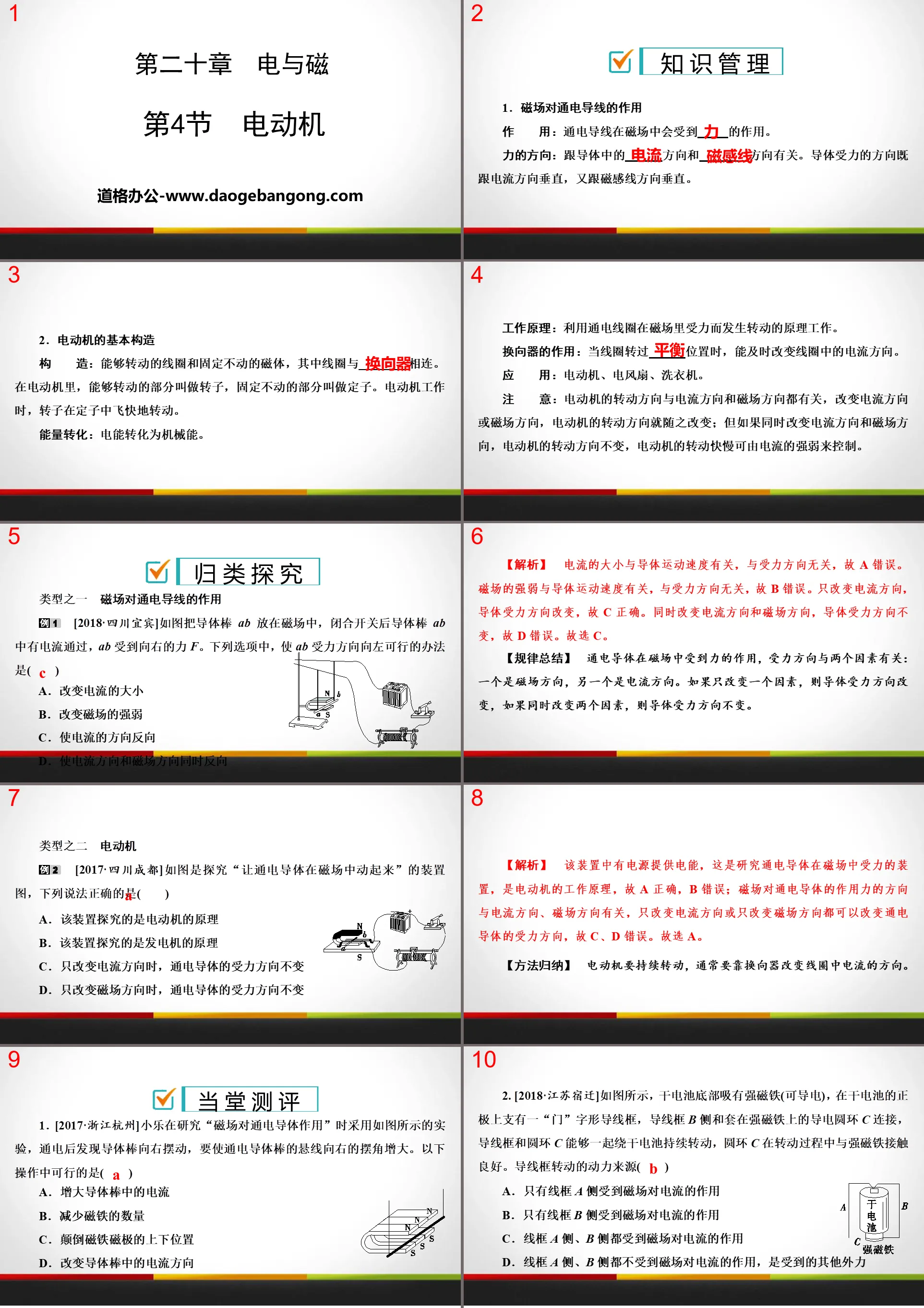
1. Effect of magnetic field on current-carrying wires
Effect: A current-carrying wire will experience a force in a magnetic field.
The direction of the force: related to the direction of the current in the conductor and the direction of the magnetic field lines. The direction of force on a conductor is perpendicular to both the direction of current and the direction of magnetic field lines.
2. Basic structure of electric motor
Construction: a rotating coil and a fixed magnet, where the coil is connected to a commutator. In an electric motor, the rotating part is called the rotor, and the fixed part is called the stator. When the motor is working, the rotor rotates rapidly in the stator.
Energy conversion: electrical energy is converted into mechanical energy.
Working principle: It works based on the principle that the energized coil is forced to rotate in the magnetic field.
The function of the commutator: when the coil rotates through the equilibrium position, it can change the direction of the current in the coil in time.
Applications: electric motors, electric fans, washing machines.
Note: The direction of rotation of the motor is related to both the direction of the current and the direction of the magnetic field. If the direction of the current or the direction of the magnetic field is changed, the direction of rotation of the motor will change accordingly; but if the direction of the current and the direction of the magnetic field are changed at the same time, the direction of rotation of the motor will not change. The speed of rotation can be controlled by the strength of the current.
Electric motor PPT, part 2: classification and exploration
Type one: The effect of magnetic field on current-carrying wires
[2018•Sichuan Yibin]As shown in the figure, the conductor bar ab is placed in the magnetic field. After the switch is closed, a current flows through the conductor bar ab, and ab receives a force F to the right. Among the following options, the feasible way to make the direction of force ab to the left is (C)
A. Change the size of the current
B. Change the strength of the magnetic field
C. reverse the direction of current
D. Reverse the direction of current and magnetic field at the same time
[Analysis] The size of the current is related to the speed of the conductor and has nothing to do with the direction of the force, so A is wrong. The strength of the magnetic field is related to the speed of the conductor and has nothing to do with the direction of the force, so B is wrong. Only the direction of the current changes, and the direction of the force on the conductor changes, so C is correct. When the direction of the current and the direction of the magnetic field are changed at the same time, the direction of the force on the conductor remains unchanged, so D is wrong. So choose C.
[Summary of rules] A current-carrying conductor is acted upon by a force in a magnetic field, and the direction of the force is related to two factors: one is the direction of the magnetic field, and the other is the direction of the current. If only one factor is changed, the direction of the force on the conductor changes; if two factors are changed at the same time, the direction of the force on the conductor remains unchanged.
Type 2: Electric motor
[2017•Chengdu, Sichuan]The picture below is a diagram of a device that explores "making energized conductors move in a magnetic field". Which of the following statements is correct (A)
A. This device explores the principles of electric motors
B. This device explores the principle of a generator
C. When only the direction of the current is changed, the direction of the force on the current-carrying conductor remains unchanged.
D. When only the direction of the magnetic field is changed, the direction of the force on the current-carrying conductor remains unchanged.
[Analysis] There is a power supply in this device to provide electrical energy. This is a device that studies the force exerted on a energized conductor in a magnetic field. It is the working principle of an electric motor, so A is correct and B is wrong; the direction of the force exerted by the magnetic field on the energized conductor is the same as the direction of the current. It is related to the direction of the magnetic field. Changing only the direction of the current or only changing the direction of the magnetic field can change the force direction of the energized conductor, so C and D are wrong. Therefore choose A.
[Method Summary] In order for the motor to continue to rotate, it usually relies on a commutator to change the direction of the current in the coil.
Electric motor PPT, the third part: evaluation in class
1. [2017•Zhejiang Hangzhou] Xiaole used the experiment as shown in the figure when studying the "effect of magnetic field on energized conductors". After energizing, he found that the conductor rod swung to the right. To make the suspension line of the energized conductor rod move toward The right swing angle increases. The following operations are possible (A)
A. Increase the current in the conductor rod
B. Reduce the number of magnets
C. Reversing the up and down positions of the magnet poles
D. Change the direction of current in a conductor rod
2. [2018•Jiangsu Suqian]As shown in the picture, there is a strong magnet (which can conduct electricity) at the bottom of the dry battery. There is a "door" shaped lead frame on the positive electrode of the dry battery. The B side of the lead frame and the sleeve The conductive ring C on the strong magnet is connected. The lead frame and the ring C can continue to rotate around the dry battery together. The ring C has good contact with the strong magnet during the rotation process. The power source for the rotation of the lead frame (B)
A. Only side A of the wireframe is affected by the magnetic field on the current
B. Only the B side of the wire frame is affected by the magnetic field on the current
C. Both sides A and B of the wire frame are affected by the magnetic field on the current.
D. Sides A and B of the wire frame are not affected by the magnetic field on the current, but other external forces.
[Analysis] There is a strong magnet at the bottom of the dry battery, and there is a magnetic field around it. The B side of the lead frame is connected to the conductive ring C on the strong magnet. Then there is current flowing through the B side of the wire frame (that is, the B side of the wire frame is a current-carrying conductor). Therefore, side B of the wire frame moves due to the force exerted by the magnetic field on the current; and side A of the wire frame is not energized, so side A does not experience the force exerted by the magnetic field, so B is correct.
3. [2018•Guizhou Zunyi]As shown in the figure is the internal structure diagram of the laboratory ammeter. When the coil in the magnetic field has current passing through it, the coil will drive the pointer to deflect together. The greater the current in the coil, the greater the pointer deflection angle. Regarding this phenomenon, which of the following statements is correct (A)
A. This ammeter works on the same principle as an electric motor
B. When current passes through the coil, mechanical energy is converted into electrical energy
C. Changing the direction of the current in the coil does not change the deflection direction of the pointer
D. The greater the current in the coil, the smaller the magnetic field force on the coil.
[Analysis] The internal structure of the ammeter shows the making principle of the ammeter: the energized coil is forced to rotate in the magnetic field, and the greater the current, the greater the force on the coil, and the greater the amplitude of its rotation. Therefore, the rotation amplitude of the ammeter pointer can be used to reflect the size of the current in the circuit. It can be seen from the analysis that the working principle of the ammeter is the same as that of the electric motor, so A is correct; when there is current passing through the coil, electrical energy is converted into mechanical energy, so B is wrong; changing the direction of the current in the coil will change its direction of rotation, so C Wrong; there is a magnetic field around the energized wire. The greater the current, the stronger the magnetic field around the coil, and the greater the magnetic field force on the coil, so D is wrong.
4. [2017•Yueyang, Hunan]As shown in the figure, when the switch is closed, the conductor ab moves to the left. If only the direction of the current is changed, ab moves to the right (optional "left" or "right"). This is the principle. Can be made into a motor (optional "motor" or "generator").
5. [2018•Hunan Yiyang]As shown in the picture, this is the schematic diagram of an electric motor (optional "generator" or "motor"). If the S pole and N pole of the magnet in the picture are exchanged, If everything else remains unchanged, the direction of the force on side a of the coil will change (optional "change", "no change" or "may change or may not change").
Electric motor PPT, part 4: layered operations
1. [2018•Zhejiang Jiaxing]The experimental device as shown in the picture can be used ( D )
A. Study the relationship between the direction of the induced current and the direction of the magnetic field
B. Study what factors are related to the magnetism of electromagnets
C. Study how generators work
D. Study what factors are related to the force experienced by a current-carrying conductor in a magnetic field
2. [2018•Shandong Zibo]The picture shows an experimental device to explore "the force exerted by an energized wire in a magnetic field". When the circuit is turned on instantly, the originally stationary wire ab moves to the right. To make wire ab move to the left, the feasible measures are (A)
A. Reverse the N and S poles of the magnet
B. Increase supply voltage
C. Change to a stronger magnet
D. Reverse the N and S poles of the magnet and change the direction of the current at the same time
3. [2018•Guangxi Baise]As shown in the figure, what can be used to study the working principle of the motor is ( C )
4. [2018•Jiangsu Yangzhou]When installing a DC motor model, you need to change the rotation direction of the DC motor. You can ( A )
A. Reverse the N and S poles of the magnet
B. Reverse the positive and negative poles of the power supply and the N and S poles of the magnet at the same time
C. Change the strength of magnetism
D. Change the magnetic strength and current size
5. [2018•Hubei Enshi Prefecture]As shown in the picture, after closing the switch, the metal rod ab on the track will move. In this process, the energy conversion is electrical energy into mechanical energy.
6. [2017•Mianyang, Sichuan]A rectangular coil is placed between the two poles of a hoof magnet. When it is first energized, it twists in the direction under the action of the magnetic field as shown in Figure A. Now place the coil between the hoof-shaped solenoid as shown in Figure B. A and b are the interfaces between the solenoid and the power supply. A classmate performed the following four operations:
① Connect a to the positive pole and b to the negative pole. The current in the coil flows in the same direction as the current in Figure A;
②B is connected to the positive pole, a is connected to the negative pole, and the current in the same direction as the current in Figure A passes through the coil;
③Connect a to the positive pole, b to the negative pole, and a current in the opposite direction to the current in Figure A passes through the coil;
④B is connected to the positive pole, a is connected to the negative pole, and a current in the opposite direction to the current in Figure A flows through the coil.
When the coil is first energized, the twisting direction is the same as the twisting direction shown in Figure A (D)
A. ① and ③ B. ② and ④
C. ① and ④ D. ② and ③
Keywords: Free download of PPT courseware for ninth-grade physics from People's Education Edition, download of electric motor PPT, download of electricity and magnetism PPT, .PPT format;
For more information about the "Electricity and Magnetic Motors" PPT courseware, please click on the Electricity and Magnetic Motors ppt tab.
"Magnetism Generates Electricity" Electricity and Magnetism PPT:
"Magnetism Generates Electricity" Electricity and Magnetism PPT Part One Content: Knowledge Management 1. Electromagnetic induction phenomenon: When a part of a conductor in a closed circuit moves to cut magnetic field lines in a magnetic field, a current (induced current) is generated in the conductor. This phenomenon is called electromagnetic induction. The electricity generated...
"Electromagnet Electromagnetic Relay" Electricity and Magnetism PPT:
"Electromagnet Electromagnetic Relay" Electricity and Magnetism PPT Part One Content: Knowledge Management 1. Electromagnet composition: It is a solenoid with an iron core, which is composed of a coil and an iron core. There is an iron core in the electromagnet to enhance the magnetism of the electromagnet. Strong magnetism..
"Electric Magnetism" Electricity and Magnetism PPT:
"Electric Magnetism" Electricity and Magnetism PPT Part One Content: Knowledge Management 1. Oersted's experiment conclusion: There is a magnetic field around a current-carrying wire, and the direction of the magnetic field is related to the direction of the current. Significance: Oersted's experiment was the first to reveal the close connection between electrical phenomena and magnetic phenomena.
File Info
Update Time: 2024-09-09
This template belongs to Physics courseware People's Education Edition Ninth Grade Physics Complete Book industry PPT template
"Electric Motor" Electricity and Magnetism PPT Simple campus recruitment activity planning plan summary enterprise and institution recruitment publicity lecture PPT template is a general PPT template for business post competition provided by the manuscript PPT, simple campus recruitment activity planning plan summary enterprise and institution recruitment promotion Lecture PPT template, you can edit and modify the text and pictures in the source file by downloading the source file. If you want more exquisite business PPT templates, you can come to grid resource. Doug resource PPT, massive PPT template slide material download, we only make high-quality PPT templates!
Tips: If you open the template and feel that it is not suitable for all your needs, you can search for related content "Electric Motor" Electricity and Magnetism PPT is enough.
How to use the Windows system template
Directly decompress the file and use it with office or wps
How to use the Mac system template
Directly decompress the file and use it Office or wps can be used
Related reading
For more detailed PPT-related tutorials and font tutorials, you can view: Click to see
How to create a high-quality technological sense PPT? 4 ways to share the bottom of the box
Notice
Do not download in WeChat, Zhihu, QQ, built-in browsers, please use mobile browsers to download! If you are a mobile phone user, please download it on your computer!
1. The manuscript PPT is only for study and reference, please delete it 24 hours after downloading.
2. If the resource involves your legitimate rights and interests, delete it immediately.
3. Contact information: service@daogebangong.com
"Electric Motor" Electricity and Magnetism PPT, due to usage restrictions, it is only for personal study and reference use. For commercial use, please go to the relevant official website for authorization.
(Personal non-commercial use refers to the use of this font to complete the display of personal works, including but not limited to the design of personal papers, resumes, etc.)
Preview
Related Search:
"Electric Motor" Electricity and Magnetism PPT
2024-09-09
Copyright statement: This material is compiled and released by the user of Daoge Resources. The copyright belongs to the author. For commercial use, please contact the copyright owner. If there is any infringement, please contact the webmaster to remove the resource.
Download Points: 0.00
Free Download
Upgrade VIP
Favorite
Views: 3236 / Downloads: 170