People's Education Edition Physics for Grade 8, Volume 2
People's Education Edition Ninth Grade Physics Complete Book
Shanghai Science Edition Ninth Grade Physics
People's Education Edition Physics for Grade 8, Volume 1
Shanghai Science Edition 8th Grade Physics
Beijing Normal University eighth grade physics volume one
Lu Jiao Edition Ninth Grade Physics Volume 2
Lu Jiao Edition Ninth Grade Physics Volume 1
Beijing Normal University Ninth Grade Physics Volume 1
Guangdong and Shanghai Edition Ninth Grade Physics Volume 1
Lu Ke Edition High School Physics Compulsory Course One
People's Education Press High School Physics Compulsory Course II
Lu Jiao Edition Eighth Grade Physics Volume 2
Beijing Normal University Ninth Grade Physics Volume 2
Guangdong and Shanghai Edition Ninth Grade Physics Volume 2
Guangdong and Shanghai version of eighth grade physics volume 2

| Category | Format | Size |
|---|---|---|
| People's Education Edition Ninth Grade Physics Complete Book | pptx | 6 MB |

"Voltage" Voltage Resistance PPT Courseware Download
2024-09-30
Copyright statement: This material is compiled and released by the user of Daoge Resources. The copyright belongs to the author. For commercial use, please contact the copyright owner. If there is any infringement, please contact the webmaster to remove the resource.
Download Points: 0.00
Free Download
Upgrade VIP
Favorite
Views: 2267 / Downloads: 919
Description
"Voltage" Voltage Resistance PPT Courseware Download
Part One: Guidance Design
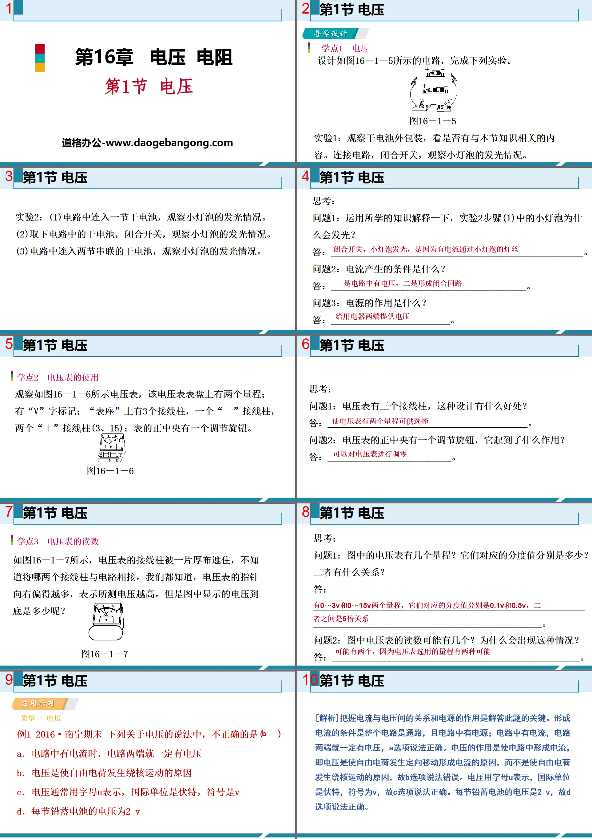
Learning Point 1 Voltage
Design the circuit shown in Figure 16-1-5 and complete the following experiments.
Experiment 1: Observe the outer packaging of dry batteries to see if there is any content related to the knowledge in this section. Connect the circuit, close the switch, and observe the glow of the small bulb.
Experiment 2: (1) Connect a dry battery to the circuit and observe the light emission of the small light bulb.
(2) Remove the dry battery from the circuit, close the switch, and observe the glow of the small bulb.
(3) Connect two dry batteries in series to the circuit and observe the light emission of the small bulb.
think:
Question 1: Use the knowledge you have learned to explain why the small light bulb in step (1) of Experiment 2 glows?
answer:_____________________________________________________.
Question 2: What are the conditions for current generation?
answer:_________________________________________.
Question 3: What is the function of power supply?
answer:_________________________.
Learning point 2: Use of voltmeter
Observe the voltmeter shown in Figure 16-1-6. There are two ranges on the dial of the voltmeter; there is a "V" mark; there are three terminals on the "meter base", one "-" terminal and two "+" terminal (3, 15); there is an adjustment knob in the center of the watch.
think:
Question 1: The voltmeter has three binding posts. What are the benefits of this design?
answer:__________________________________________.
Question 2: There is an adjustment knob in the center of the voltmeter. What does it do?
answer:__________________________.
Learning point 3: Voltmeter readings
As shown in Figure 16-1-7, the terminals of the voltmeter are covered by a piece of thick cloth. It is not known which two terminals are connected to the circuit. We all know that the more the voltmeter pointer moves to the right, the higher the measured voltage. But what exactly is the voltage shown in the picture?
think:
Question 1: How many ranges does the voltmeter in the picture have? What are their corresponding graduation values? What is the relationship between the two?
answer:_______________________________________________________________________________.
Question 2: How many possible readings can the voltmeter in the picture have? Why does this happen?
answer:____________________________________________________.
Voltage PPT, Part 2: Application Examples
Type 1 Voltage
Example 1 2016·Nanning Final Of the following statements about voltage, which one is incorrect ( )
A. When there is current in a circuit, there must be voltage across the circuit
B. Voltage is what causes free charges to move around the nucleus
C. Voltage is usually represented by the letter U, the SI unit is volts, and the symbol is V
D. The voltage of each lead-acid battery is 2 V
[Analysis]Understanding the relationship between current and voltage and the role of power supply are the keys to answer this question. The conditions for the formation of current are that the entire circuit is a path and there is a power supply in the circuit; if there is current in the circuit, there must be voltage at both ends of the circuit. Option A is correct. The function of voltage is to form a current in the circuit, that is, voltage is the cause of the directional movement of free charges to form a current, rather than the cause of the movement of free charges around the core, so option B is incorrect. Voltage is represented by the letter U, the international unit is volts, and the symbol is V, so option C is correct. The voltage of each lead-acid battery is 2 V, so option D is correct.
Type 2 Use of voltmeter
Example 2 When practicing using a voltmeter in the laboratory, in order to measure the voltage at both ends of the light bulb L2, four students connected the circuits as shown in Figure 16-1-3. The correct one is ( )
[ Analysis In option A, the voltmeter is connected in parallel with L2, but the "+" and "-" terminals are connected incorrectly, and the range selection is wrong; in option B, the voltmeter is connected in parallel with both ends of L1, and the voltage at both ends of L1 is measured; option C In option D, the voltmeter is connected in parallel with L2, and the range of the voltmeter is selected correctly, and the "+" and "-" terminals are connected correctly; in option D, the voltmeter is connected in series to the circuit, which does not comply with the usage rules of the voltmeter.
Type 3 voltmeter reading
Example 3 Figure 16-1-4 shows the dial of a voltmeter. The correct reading below is ( )
A. If the measurement range is 0~3 V, the reading is 1.7 V
B. If the measurement range is 0~15 V, the reading is 9.7 V
C. If the measurement range is 0~3 V, the reading is 1.35 V
D. If the measurement range is 0~15 V, the reading is 5.7 V
[ Analysis The voltage value that can be read at the position is 8.5 V; if the selected range of the voltmeter is 0 to 3 V, the corresponding division value is 0.1 V, and the voltage value that can be read according to the position pointed by the pointer is 1.7 V. Based on the above analysis, only option A is correct.
Type 4 Determination of Electric Meter
Example 4 As shown in Figure 16-1-6, bulbs L1 and L2 both emit light normally. An ammeter or voltmeter can be connected to the "○" position to measure the current or voltage in the circuit. The correct statement below is ( )
A. a is an ammeter, b is a voltmeter, and c is an ammeter.
B. a is a voltmeter, b is a voltmeter, and c is an ammeter.
C. a is an ammeter, b is an ammeter, and c is a voltmeter.
D. a is the ammeter, b is the ammeter, c is the ammeter
[ Analysis is an ammeter, and a is connected in parallel with L1, so a must be a voltmeter, so option B is correct.
[Method guidance]Three methods to attack, cleverly determine the type of electric meter
(1) Direct observation method: Directly observe the way the meter is connected to the circuit. If the meter is connected in series with other components, the meter is an ammeter; if the meter is connected in parallel with other components, the meter is a voltmeter.
(2) Electric meter deletion method: If deleting an electric meter in the circuit does not affect the work of all electrical appliances in the circuit, then the meter is a voltmeter; if it affects the work of one electrical appliance or all electrical appliances in the circuit, then This meter is an ammeter.
(3) Hypothesis judgment method: First assume that the electric meter in the circuit is an ammeter or voltmeter, and then analyze whether there is a fault in the circuit or whether it meets the meaning of the question. If there is no fault or it matches the meaning of the question, the assumption is correct; if there is a circuit fault such as an open circuit or short circuit or it does not match the meaning of the question, the assumption is wrong. When judging, the internal resistance of the ammeter is very small, equivalent to a wire; the internal resistance of the voltmeter is large, it can be considered that there is no current passing through it, and it can be regarded as an open circuit in the circuit.
Voltage PPT, Part 3: Class Feedback
1. When studying the role of voltage, we can introduce the analogy of "water path" with "circuit". As shown in Figure 12-1, if the water pump is compared to the power supply, the valve can be compared to ________, the turbine can be compared to ________, the water pipe can be compared to ________, the water pressure can be compared to __________, and the water flow can be compared to ____________.
2. The power supply is the device that provides ________, and the voltage is the cause of the directional movement of ________ to form ________. When there is voltage in the circuit, there is current in ________, and when there is current in the circuit, there is voltage in ________. (Please fill in "Definitely" or "Not necessarily" in the last two blanks)
3. Please fill in the blanks below.
(1)0.54 kV=____________mV. (2)13.5 mV=____________V.
4. The power supply voltage of household circuits in our country is ________, the voltage that is safe for the human body is ____________, the voltage of a new dry battery is ________, and the voltage of a new lead-acid battery is ________.
5. It is known that the voltage at both ends of a small light bulb that is emitting light is about 2 V. Xiao Ming wants to use the voltmeter as shown in Figure 12-2 to measure the voltage at both ends of the small light bulb. The terminals he should connect are "______" and "______" And make the voltmeter _________ with the small light bulb (optional "series" or "parallel").
6. As shown in Figure 12-3, the scale value corresponding to each small division deflection of the pointer of table A is ________V, and it has been deflected ________ small divisions, so the corresponding indication is ________V; similarly, the pointer of table B The scale value corresponding to each deflection of 1 small division is ________V, and ________ small divisions have been deflected, so the corresponding indication is ________V.
7. As shown in Figure 12-4, in the five circuit diagrams A, B, C, D, and E, the diagram that uses a voltmeter to measure the total voltage of the circuit is ________, the diagram that measures the voltage at both ends of L1 is ________, and the diagram that measures the voltage at both ends of L2 is ________. The graph of terminal voltage is _________.
[ Analysis The terminals are connected incorrectly; as can be seen from Figure C, the voltmeter is connected in parallel to both ends of the bulb L1. The positive and negative terminals of the voltmeter are connected correctly, and the voltage at both ends of the bulb L1 can be measured; as can be seen from Figure D, the voltmeter is connected in series. In the circuit, the connection method is wrong; as shown in Figure E, the voltmeter is connected in parallel to both ends of the bulb L2. The positive and negative terminals of the voltmeter are connected correctly, and the voltage at both ends of the bulb L2 can be measured.
Keywords: Free download of PPT courseware for ninth-grade physics from People's Education Edition, Voltage PPT download, Voltage resistance PPT download, .PPT format;
For more information about the "Voltage Resistance Voltage" PPT courseware, please click the Voltage Resistance ppt Voltage ppt tag.
"Voltage" Voltage Resistance PPT Free Courseware:
"Voltage" Voltage Resistance PPT Free Courseware Part One: A Classification Practice of Knowledge Points Knowledge Point 1 Voltage 1. Voltage is the cause of _________, that is, voltage causes free charges in the circuit to ____________ to form current, and _________ provides voltage..
"Voltage" Voltage Resistance PPT Teaching Courseware:
"Voltage" Voltage Resistance PPT Teaching Courseware Part One: Tutoring by Famous Teachers 1. Voltage is what causes current to form. 2. To obtain a continuous current in a circuit, two conditions must be met: (1) there is a power supply to provide voltage; (2) the circuit is a path. Analysis of typical examples [Example]..
《Voltage》Voltage resistance PPT download:
"Voltage" Voltage Resistance PPT Download Part One Content: Learning Objectives 1. Know the role of voltage and that a power supply is a device that provides voltage; know the unit of voltage and its conversion, and remember the voltage values of dry batteries and household circuits. 2. Understand the voltmeter and its...
File Info
Update Time: 2024-09-30
This template belongs to Physics courseware People's Education Edition Ninth Grade Physics Complete Book industry PPT template
"Voltage" Voltage Resistance PPT Courseware Download Simple campus recruitment activity planning plan summary enterprise and institution recruitment publicity lecture PPT template is a general PPT template for business post competition provided by the manuscript PPT, simple campus recruitment activity planning plan summary enterprise and institution recruitment promotion Lecture PPT template, you can edit and modify the text and pictures in the source file by downloading the source file. If you want more exquisite business PPT templates, you can come to grid resource. Doug resource PPT, massive PPT template slide material download, we only make high-quality PPT templates!
Tips: If you open the template and feel that it is not suitable for all your needs, you can search for related content "Voltage" Voltage Resistance PPT Courseware Download is enough.
How to use the Windows system template
Directly decompress the file and use it with office or wps
How to use the Mac system template
Directly decompress the file and use it Office or wps can be used
Related reading
For more detailed PPT-related tutorials and font tutorials, you can view: Click to see
How to create a high-quality technological sense PPT? 4 ways to share the bottom of the box
Notice
Do not download in WeChat, Zhihu, QQ, built-in browsers, please use mobile browsers to download! If you are a mobile phone user, please download it on your computer!
1. The manuscript PPT is only for study and reference, please delete it 24 hours after downloading.
2. If the resource involves your legitimate rights and interests, delete it immediately.
3. Contact information: service@daogebangong.com
"Voltage" Voltage Resistance PPT Courseware Download, due to usage restrictions, it is only for personal study and reference use. For commercial use, please go to the relevant official website for authorization.
(Personal non-commercial use refers to the use of this font to complete the display of personal works, including but not limited to the design of personal papers, resumes, etc.)
Preview
Related Search:
"Voltage" Voltage Resistance PPT Courseware Download
2024-09-30
Copyright statement: This material is compiled and released by the user of Daoge Resources. The copyright belongs to the author. For commercial use, please contact the copyright owner. If there is any infringement, please contact the webmaster to remove the resource.
Download Points: 0.00
Free Download
Upgrade VIP
Favorite
Views: 2267 / Downloads: 919