| Category | Format | Size |
|---|---|---|
| People's Education Edition Ninth Grade Physics Complete Book | pptx | 6 MB |

"Laws of Voltage in Series and Parallel Circuits" Voltage Resistance PPT Courseware Download
Description
"Laws of Voltage in Series and Parallel Circuits" Voltage Resistance PPT Courseware Download
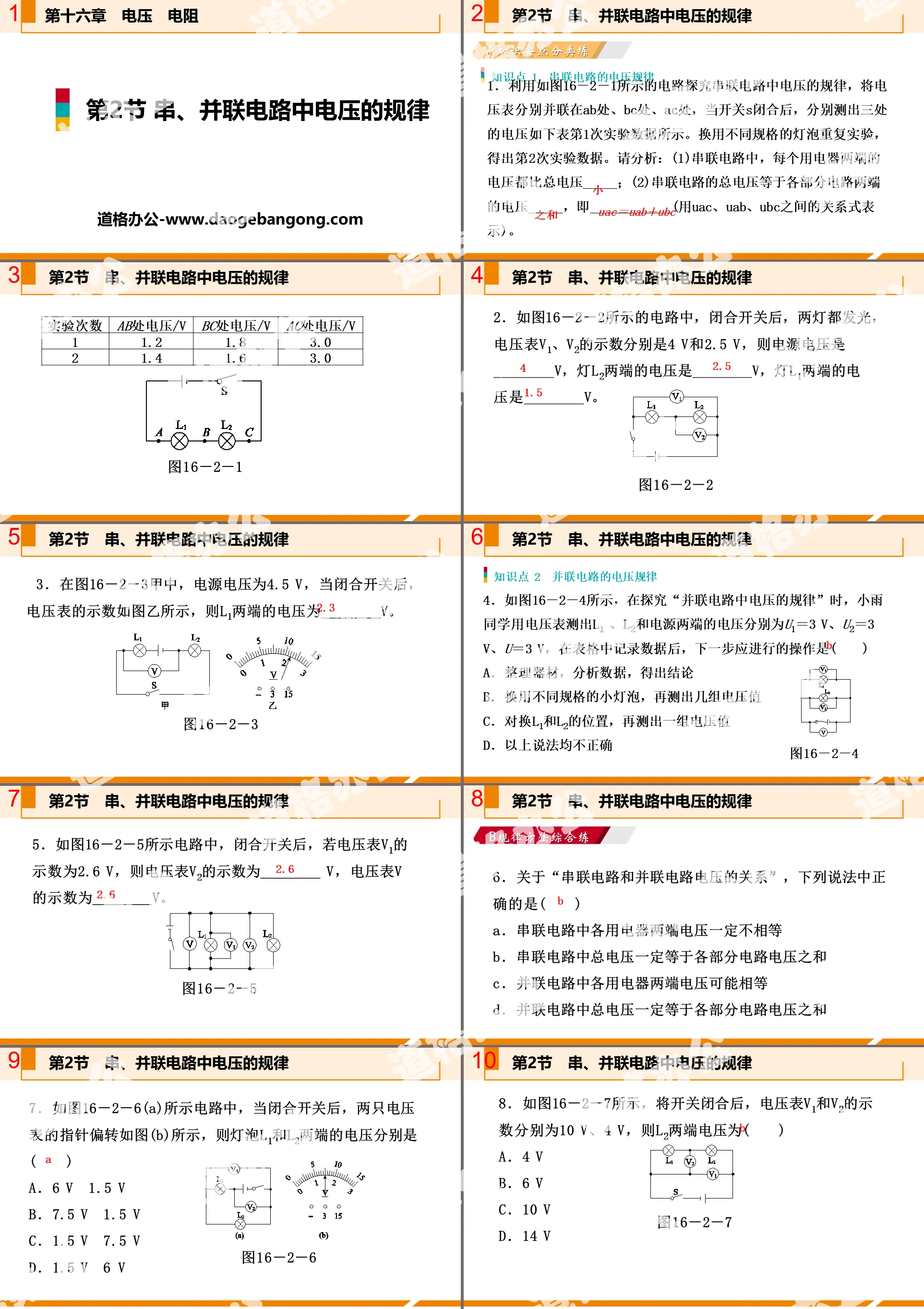
Part One Content: A Classification Practice of Knowledge Key Points
Knowledge point 1 Voltage rules of series circuits
1. Use the circuit shown in Figure 16-2-1 to explore the voltage pattern in the series circuit. Connect the voltmeters in parallel at AB, BC, and AC. When the switch S is closed, measure the voltages at the three locations as follows: The data from the first experiment are shown. Repeat the experiment using light bulbs of different specifications to obtain the second experimental data. Please analyze: (1) In a series circuit, the voltage across each electrical appliance is _____ than the total voltage; (2) The total voltage of the series circuit is equal to the voltage across each part of the circuit _____, that is, ____________ (use UAC, UAB , the relationship expression between UBC).
2. In the circuit shown in Figure 16-2-2, after the switch is closed, both lamps light up. The readings of the voltmeters V1 and V2 are 4 V and 2.5 V respectively. Then the power supply voltage is ________V, and the voltage across the lamp L2 is is ________V, the voltage across lamp L1 is ________V.
3. In Figure 16-2-3A, the power supply voltage is 4.5 V. When the switch is closed, the voltmeter indicates as shown in Figure B, then the voltage across L1 is ________V.
Knowledge point 2: Voltage rules of parallel circuits
4. As shown in Figure 16-2-4, when exploring the "law of voltage in parallel circuits", Xiaoyu used a voltmeter to measure the voltages at L1, L2 and the power supply terminals as U1=3 V, U2=3 V, U =3 V, after recording the data in the table, the next step is ()
A. Organize equipment, analyze data, and draw conclusions
B. Use small light bulbs of different specifications and measure several sets of voltage values.
C. Swap the positions of L1 and L2, and then measure a set of voltage values.
D. None of the above statements are correct
5. In the circuit shown in Figure 16-2-5, after the switch is closed, if the reading of voltmeter V1 is 2.6 V, then the reading of voltmeter V2 is ________V, and the reading of voltmeter V is ________V.
The law of voltage in series and parallel circuits PPT, the second part of the content: Comprehensive practice of the B law method
6. Regarding "the relationship between voltages in series circuits and parallel circuits", which of the following statements is correct ()
A. The voltages at both ends of each electrical appliance in a series circuit must not be equal
B. The total voltage in a series circuit must be equal to the sum of the voltages in each part of the circuit
C. The voltages at both ends of each electrical appliance in a parallel circuit may be equal
D. The total voltage in a parallel circuit must be equal to the sum of the voltages of each part of the circuit
7. In the circuit shown in Figure 16-2-6(a), when the switch is closed, the pointers of the two voltmeters deflect as shown in Figure (b), then the voltages across the bulbs L1 and L2 are ()
A. 6 V | 1.5 V
B. 7.5V 1.5V
C. 1.5V 7.5V
D. 1.5 V | 6 V
8. As shown in Figure 16-2-7, after the switch is closed, the readings of voltmeters V1 and V2 are 10 V and 4 V respectively, then the voltage across L2 is ()
A. 4 V
B. 6V
C. 10 V
D. 14 V
9. In the circuit shown in Figure 16-2-8, when the switch is closed, the reading of voltmeter V1 is 7.5 V, and the reading of voltmeter V2 is 9 V. If the power supply voltage is 12 V, then the voltage across L2 yes()
A. 4.5 V
B. 5.5 V
C. 3 V
D. 2 V
10. In the circuit shown in Figure 16-2-9A, the voltmeter measures the voltage at both ends of _______ (optional "L1" or "L2"). The indication of the voltmeter is as shown in Figure B. If the power supply voltage is 6 V, then the voltage across lamp L1 is ________V.
11. In the experimental operation exam, classmate Wu Li was selected for the experiment "Exploring the Laws of Voltage in Series Circuits". The experimental process is as follows:
(1) When she checked the experimental equipment, she found that the pointer position of the voltmeter was as shown in Figure 16-2-10A. Then the next operation she wanted to perform on the voltmeter was __________.
(2) After the problem is solved, start connecting the circuit as shown in Figure B. When you try the switch, you find that the pointer of the voltmeter deflects to the position shown in Figure A. The reason for this phenomenon on the voltmeter is ____________________.
(3) After correcting the error, she used a voltmeter to measure the voltage UAB across L1, the voltage UBC across L2, and the total voltage UAC across L1 and L2. She replaced different light bulbs and did two more experiments. The experimental data measured three times. As shown in the table below.
Please answer the following questions based on her experimental process and relevant data:
①The shortcomings in the table designed above are ____________________.
② Analyze the data in the table and draw the experimental conclusion that ____________________________________________.
12. In order to explore the rules of voltage in parallel circuits, the equipment provided in the laboratory include: dry battery pack (voltage is 3 V), voltmeter, multiple small light bulbs, switches, and several wires.
(1) Use stroke lines instead of wires to complete the circuit connection in Figure 16-2-11A. Requirements: Measure the voltage at both ends of L1 with a voltmeter.
(2) After the circuit is connected correctly, the experiment is carried out. A group measures the voltage at both ends of the light bulbs L1 and L2 and the total voltage of the parallel circuit. The voltage expression numbers are the same, as shown in Figure B, and its value is ________V. Based on this set of data, the team derived the laws of voltage in parallel circuits. What do you think is an omission in the experiment? __________________.
The law of voltage in series and parallel circuits PPT, the third part of the content: Practical practice of C high frequency examination questions
13. [2017·Liuzhou]In the circuit shown in Figure 16-2-12, when the switch S is closed, the indications of the voltmeters V, V1, and V2 are U, U1, and U2 respectively. The correct relationship between
A. U=U1=U2 B. U>U1+U2
C. U<U1+U2 D. U=U1+U2
14. [2017·Yangzhou]In the activity "Exploring the Characteristics of Voltage in Series Circuits":
(1) As shown in Figure 16-2-13, when connecting a circuit, at least _______ wires are required; small light bulbs with specifications of ________ (optional "same" or "different") should be selected in the experiment.
(2) When measuring the voltage at both ends of L1, close the switch and find that the voltage indication is zero. The reason may be ______________ (just fill in one).
(3) Xiaofang keeps the B connection point of the voltmeter stationary, disconnects only the A connection point, and changes it to the C connection point to measure the voltage at both ends of L2. Can she measure the voltage across L2? ______, the reason is ____________________.
(4) Xiao Ming measured the voltages between AB, BC, and AC respectively and recorded them in the following table. After analyzing the experimental data, he concluded that the total voltage of the series circuit is equal to the sum of the voltages at both ends of each part of the circuit. Please evaluate Xiao Ming’s approach: ____________________, the improvement method is ____________________.
Keywords: Free download of PPT courseware for ninth-grade physics from the People's Education Press, PPT download of the law of voltage in series and parallel circuits, PPT download of voltage and resistance, .PPT format;
For more information about the PPT courseware "The Laws of Voltage in Series and Parallel Circuits of Voltage Resistors", please click the Laws of Voltage in Series and Parallel Circuits of Voltage Resistors ppt ppt tag.
《Resistance》Voltage resistance PPT:
"Resistor" Voltage Resistance PPT Part One Content: Knowledge Points Basic Knowledge Point 1 Resistor 1. As shown in the figure, when the copper wire is connected to the circuit, the small bulb is brighter; when the nickel-chromium alloy wire is connected to the circuit, the small bulb is darker. This shows that the resistance of the copper wire in the picture is less than (optional) is greater than or...
"The Laws of Voltage in Series and Parallel Circuits" Voltage Resistance PPT Teaching Courseware:
"The Laws of Voltage in Series and Parallel Circuits" Voltage Resistance PPT Teaching Courseware Part One Content: Guided Design Learning Point 1 Explore the voltage laws of series circuits, as shown in Figure 16-2-11, Xiaoli based on circuit diagram 16-2-10 , using the same specs of bulb design..
"Laws of Voltage in Series and Parallel Circuits" Voltage Resistance PPT Download (Lesson 2):
"Laws of Voltage in Series and Parallel Circuits" Voltage Resistance PPT Download (Lesson 2) Part One: Tutorials by famous teachers, key and difficult points 1. Use a voltmeter to measure the voltage across each electrical appliance in the parallel circuit. 2. Summarize the rules of voltage in parallel circuits. Code..
File Info
Update Time: 2024-06-20
This template belongs to Physics courseware People's Education Edition Ninth Grade Physics Complete Book industry PPT template
"Laws of Voltage in Series and Parallel Circuits" Voltage Resistance PPT Courseware Download Simple campus recruitment activity planning plan summary enterprise and institution recruitment publicity lecture PPT template is a general PPT template for business post competition provided by the manuscript PPT, simple campus recruitment activity planning plan summary enterprise and institution recruitment promotion Lecture PPT template, you can edit and modify the text and pictures in the source file by downloading the source file. If you want more exquisite business PPT templates, you can come to grid resource. Doug resource PPT, massive PPT template slide material download, we only make high-quality PPT templates!
Tips: If you open the template and feel that it is not suitable for all your needs, you can search for related content "Laws of Voltage in Series and Parallel Circuits" Voltage Resistance PPT Courseware Download is enough.
How to use the Windows system template
Directly decompress the file and use it with office or wps
How to use the Mac system template
Directly decompress the file and use it Office or wps can be used
Related reading
For more detailed PPT-related tutorials and font tutorials, you can view: Click to see
How to create a high-quality technological sense PPT? 4 ways to share the bottom of the box
Notice
Do not download in WeChat, Zhihu, QQ, built-in browsers, please use mobile browsers to download! If you are a mobile phone user, please download it on your computer!
1. The manuscript PPT is only for study and reference, please delete it 24 hours after downloading.
2. If the resource involves your legitimate rights and interests, delete it immediately.
3. Contact information: service@daogebangong.com
"Laws of Voltage in Series and Parallel Circuits" Voltage Resistance PPT Courseware Download, due to usage restrictions, it is only for personal study and reference use. For commercial use, please go to the relevant official website for authorization.
(Personal non-commercial use refers to the use of this font to complete the display of personal works, including but not limited to the design of personal papers, resumes, etc.)
Preview
Related Search: