People's Education Edition Physics for Grade 8, Volume 2
People's Education Edition Physics for Grade 8, Volume 1
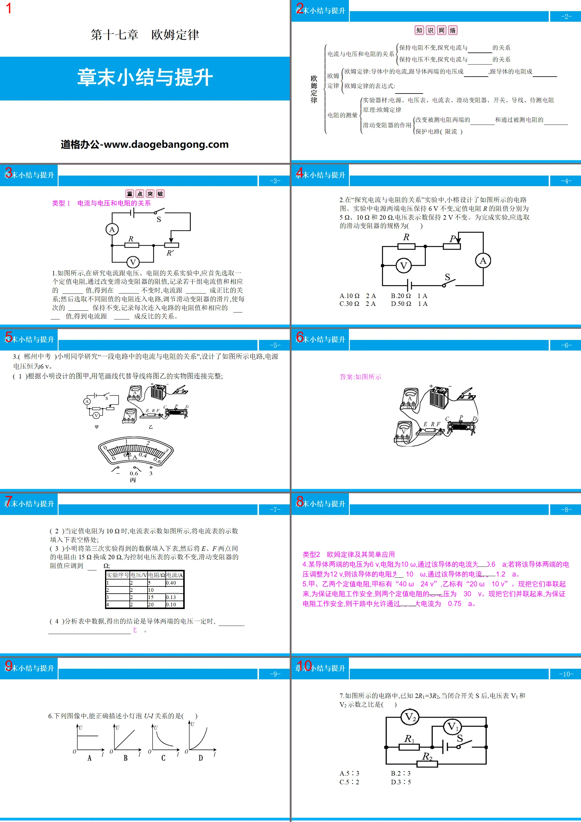
People's Education Edition Ninth Grade Physics Complete Book
Shanghai Science Edition Ninth Grade Physics
Shanghai Science Edition 8th Grade Physics
Beijing Normal University eighth grade physics volume one
Lu Jiao Edition Ninth Grade Physics Volume 2
Beijing Normal University Ninth Grade Physics Volume 1
Lu Ke Edition High School Physics Compulsory Course One
Lu Jiao Edition Ninth Grade Physics Volume 1
Guangdong and Shanghai Edition Ninth Grade Physics Volume 1
People's Education Press High School Physics Compulsory Course II
Beijing Normal University Ninth Grade Physics Volume 2
Lu Jiao Edition Eighth Grade Physics Volume 2
Lu Jiao edition eighth grade physics volume 1
Guangdong and Shanghai Edition Ninth Grade Physics Volume 2

| Category | Format | Size |
|---|---|---|
| People's Education Edition Ninth Grade Physics Complete Book | pptx | 6 MB |

"End of Chapter Summary and Improvement" Ohm's Law PPT
2024-11-09
Copyright statement: This material is compiled and released by the user of Daoge Resources. The copyright belongs to the author. For commercial use, please contact the copyright owner. If there is any infringement, please contact the webmaster to remove the resource.
Download Points: 0.00
Free Download
Upgrade VIP
Favorite
Views: 1861 / Downloads: 767
Description
"End of Chapter Summary and Improvement" Ohm's Law PPT
Part One: Key Breakthroughs
Type 1: Relationship between current, voltage and resistance
1. As shown in the figure, in the experiment to study the relationship between current, voltage and resistance, a fixed-value resistor should be selected first, and by changing the resistance value of the sliding rheostat, record several sets of current values and corresponding voltage values, and obtain the value when the resistance is different. When the voltage changes, the relationship between current and voltage is proportional; then select resistors with different resistance values and connect them to the circuit, adjust the slide of the sliding rheostat so that the voltage remains unchanged each time, and record the resistance value and corresponding value connected to the circuit each time. Current value, the relationship between current and resistance is inversely proportional.
2. In the experiment of "Exploring the Relationship between Current and Resistance", Xiaorong designed the circuit diagram as shown in the figure. During the experiment, the voltage at both ends of the power supply remained unchanged at 6 V, the resistance values of the fixed-value resistors R were 5 Ω, 10 Ω, and 20 Ω, and the voltage representation remained unchanged at 2 V. To complete the experiment, the specifications of the sliding rheostat that should be selected are (D)
A.10 Ω 2 A B.20 Ω 1 A
C.30 Ω 2 A D.50 Ω 1 A
3. (Chenzhou High School Entrance Examination) Xiao Ming studied "the relationship between current and resistance in a circuit" and designed the circuit as shown in the figure. The power supply voltage is always 6 V.
(1) According to the drawing A designed by Xiao Ming, use stroke lines instead of wires to completely connect the physical drawing of drawing B;
(2) When the fixed value resistance is 10 Ω, the current indication is as shown in the figure. Fill in the blanks in the table below with the ammeter indication;
(3) Xiao Ming fills in the data obtained from the third experiment into the table below, and then changes the resistance between points E and F from 15 Ω to 20 Ω. In order to control the voltmeter’s display unchanged, the resistance of the sliding rheostat is It should be adjusted to 40Ω;
Experiment No. Voltage/V Resistance/Ω Current/A
1 2 5 0.40
2 2 10 0.20
3 2 15 0.13
4 2 20 0.10
(4) Analyzing the data in the table, the conclusion is that when the voltage at both ends of the conductor is constant, the current in the conductor is inversely proportional to the resistance of the conductor.
Type 2 Ohm’s law and its simple applications
4. The voltage at both ends of a conductor is 6 V, the resistance is 10 Ω, and the current passing through the conductor is 0.6 A; if the voltage at both ends of the conductor is adjusted to 12 V, the resistance of the conductor is 10 Ω, and the current passing through the conductor is 10 Ω. The current is 1.2 A.
5. There are two fixed-value resistors A and B. A is marked with "40 Ω | 24 V" and B is marked with "20 Ω | 10 V". Now connect them in series. In order to ensure the safety of the resistor operation, the total voltage of the two fixed-value resistors is 30V. Now connect them in parallel. In order to ensure the safety of the resistor operation, the maximum current allowed to pass through the main circuit is 0.75 A.
End-of-Chapter Summary and Improvement PPT, Part 2: Experimental Activities
Experiment 1: Explore the relationship between current, voltage, and resistance
Experimental circuit diagram
1. Explore the relationship between current and voltage
(1) Experimental method: close the switch, adjust the sliding rheostat to change the voltage at both ends of R, and record the reading of the ammeter.
(2) Experimental conclusion: The resistance is constant and the current is proportional to the voltage.
2. Explore the relationship between current and resistance
(1) Experimental method: Replace resistors with different resistance values, adjust the slider of the sliding rheostat so that the voltage at both ends of the resistor R remains unchanged, measure multiple times, and record the display of the ammeter.
(2) Experimental conclusion: When the voltage is constant, the current is inversely proportional to the resistance.
[For training]
1. When Xiao Ming did the experiment of "exploring the relationship between current and voltage", he prepared the following equipment: two dry batteries (1.5 V), ammeter (0~0.6 A (A), voltmeter (0~3 V 0~15 V ), sliding rheostat ( 20 ( A ), fixed value resistor ( 5 Ω ), switches, and several wires. Conduct the experiment according to the circuit diagram shown in Figure A.
(1) During the experiment, to make the voltmeter indication gradually increase, the sliding varistor slide P should move toward the A (optional "A" or "B") end;
(2) During the experiment, the ammeter’s indication is as shown in Figure B. At this time, the current in the circuit is 0.5 A;
(3) In the experiment, by adjusting the sliding varistor slide P, the different currents passing through the fixed value resistor R and the corresponding voltage values were measured as shown in the table. After reading it, the teacher said that one of them was wrong, so the error was the first time. ,The reason is that the minimum value of the voltmeter is 0.6 V.
Experiment 2: Measure resistance by voltammetry
1. Experimental principle: R=?/?.
2. Experimental equipment
Power supply, switch, wire, resistance to be measured, sliding rheostat, ammeter, voltmeter.
3. Experimental circuit diagram
[For training]
2. Figure A is an experimental circuit diagram for measuring the resistance of a small light bulb using voltammetry. It is known that the working voltage of the small light bulb is 2.5 V and the maximum resistance of the sliding rheostat is 20 Ω.
(1) Please use pen-drawn lines instead of wires to complete the physical circuit connection in Figure A (it is required that the wires do not cross and the bulb turns on when the slider P slides to the left after closing the switch);
(2) Before closing the switch, the sliding piece of the sliding rheostat should be placed at end B (optional "end A", "end B" or "center of AB");
(3) Move the slider P. When the small bulb emits light normally, the ammeter reading is as shown in Figure B. Then the ammeter reading is 0.3 A and the resistance of the small bulb is 8.3 Ω (keep one decimal place);
(4) During the experimental operation, the small bulb was accidentally damaged and an open circuit occurred. No matter how the slider P was moved, the voltmeter pointer almost moved (optional "almost motionless" or "obvious deflection")
End-of-Chapter Summary and Improvement PPT, Part Three: Connection between Junior High School and High School
1. Ammeter modification: The ammeter is modified from a small-range ammeter (meter head) connected in parallel with a small resistor. Assume that the meter resistance is n times the parallel resistance and the full bias current of the meter is Ig, then the modified range is (n+1)Ig.
2. Voltmeter modification: The voltmeter is modified from a small-range ammeter (meter head) connected in series with a large resistor. Assume that the meter resistance is one-nth of the parallel resistance and the full bias voltage of the meter is Ug, then the modified range is (n+1)Ug.
[For training]
1. A voltmeter with a range of 3 V. After connecting an 8 kΩ resistor in series, the range becomes 15 V. Then the original internal resistance of the voltmeter is 2000Ω. When using the modified voltmeter to measure the voltage at both ends of a certain circuit , and found that the pointer pointed exactly at 2 V on the original voltmeter dial, then the measured voltage was 10 V.
2. As shown in the figure, the internal structure of a laboratory ammeter is composed of an ammeter G (an ammeter with a smaller range) and a fixed-value resistor R0 connected in parallel. The function of the fixed-value resistor R0 is to shunt current. If you want to modify it to an ammeter with a larger range, the fixed value resistor R0 will be replaced with a fixed value resistor with a smaller resistance (select "larger" or "smaller").
3. In life, a voltmeter is actually equivalent to a large resistor that can display the voltage across its own ends, and an ammeter is actually equivalent to a small resistor that can display the current flowing through itself. In the voltammetric resistance measurement circuit shown in the figure, if the resistance of the voltmeter itself is 3 kΩ and the reading is 3 V; the ammeter reading is 4 mA, then the true value of the resistance to be measured R is equal to (C)
A.750 Ω B.760 Ω C.1000 Ω D.1010 Ω
Keywords: Free download of PPT courseware for ninth-grade physics from the People's Education Press, download of chapter-end summary and improvement PPT, download of Ohm's law PPT, .PPT format;
For more information about the "Ohm's Law Chapter End Summary and Improvement" PPT courseware, please click the Ohm's Law ppt Chapter End Summary and Improvement ppt tag.
"Special Method for Measuring Resistance" Ohm's Law PPT:
"Special Methods for Measuring Resistance" Ohm's Law PPT [Topic Overview] Common special methods for measuring resistance include the voltohmometric method, the amperometric method, and the substitution method. The specific measurement methods are as follows: (1) The voltohmic method refers to measuring resistance with How to measure unknown resistance using a voltmeter and a known resistance. ..
"Application of Ohm's Law in Series and Parallel Circuits" Ohm's Law PPT teaching courseware:
"Application of Ohm's Law in Series and Parallel Circuits" Ohm's Law PPT Teaching Courseware Part One Content: Knowledge Management 1. The total resistance of a series connection of resistors: The total resistance of a series circuit is equal to the sum of the resistances of each part of _____. Formula: R=R1+R2. illustrate..
"Application of Ohm's Law in Series and Parallel Circuits" Download Ohm's Law PPT (Lesson 2):
"Application of Ohm's Law in Series and Parallel Circuits" Ohm's Law PPT Download (Lesson 2) Part One Content: Knowledge Points Basic Knowledge Point 1 Resistance Characteristics of Parallel Circuits 1. As shown in the figure, when switch S is closed and opened , the ratio of the indications of the ammeter is 3:1, then the electric...
File Info
Update Time: 2024-11-09
This template belongs to Physics courseware People's Education Edition Ninth Grade Physics Complete Book industry PPT template
"End of Chapter Summary and Improvement" Ohm's Law PPT Simple campus recruitment activity planning plan summary enterprise and institution recruitment publicity lecture PPT template is a general PPT template for business post competition provided by the manuscript PPT, simple campus recruitment activity planning plan summary enterprise and institution recruitment promotion Lecture PPT template, you can edit and modify the text and pictures in the source file by downloading the source file. If you want more exquisite business PPT templates, you can come to grid resource. Doug resource PPT, massive PPT template slide material download, we only make high-quality PPT templates!
Tips: If you open the template and feel that it is not suitable for all your needs, you can search for related content "End of Chapter Summary and Improvement" Ohm's Law PPT is enough.
How to use the Windows system template
Directly decompress the file and use it with office or wps
How to use the Mac system template
Directly decompress the file and use it Office or wps can be used
Related reading
For more detailed PPT-related tutorials and font tutorials, you can view: Click to see
How to create a high-quality technological sense PPT? 4 ways to share the bottom of the box
Notice
Do not download in WeChat, Zhihu, QQ, built-in browsers, please use mobile browsers to download! If you are a mobile phone user, please download it on your computer!
1. The manuscript PPT is only for study and reference, please delete it 24 hours after downloading.
2. If the resource involves your legitimate rights and interests, delete it immediately.
3. Contact information: service@daogebangong.com
"End of Chapter Summary and Improvement" Ohm's Law PPT, due to usage restrictions, it is only for personal study and reference use. For commercial use, please go to the relevant official website for authorization.
(Personal non-commercial use refers to the use of this font to complete the display of personal works, including but not limited to the design of personal papers, resumes, etc.)
Preview
Related Search:
"End of Chapter Summary and Improvement" Ohm's Law PPT
2024-11-09
Copyright statement: This material is compiled and released by the user of Daoge Resources. The copyright belongs to the author. For commercial use, please contact the copyright owner. If there is any infringement, please contact the webmaster to remove the resource.
Download Points: 0.00
Free Download
Upgrade VIP
Favorite
Views: 1861 / Downloads: 767