1. Mission objectives
This task is a functional instruction application case. Using functional instructions can help us clarify Programming ideas. This task uses normalization and scaling instructions, which are widely used in practical applications. In addition to the interpretation of instructions, this task also involves knowledge related to analog quantities.
This task requires readers to master the following contents:
1. The relationship between analog and digital quantities
2. Wiring of temperature sensor
3. Conversion of analog quantities and actual physical quantities
4. Use of standardized instructions and scaling instructions
2. Task description
As shown in Figure 3-5-1, this temperature sensor can collect the workshop temperature. The sensor (DC0-10V) feeds back the measured data to the PLC, and the PLC can calculate the actual temperature value for display on the HMI:

Figure 3-5-1 Schematic diagram of temperature collection
3. Related knowledge
The knowledge that needs to be understood in this case includes the concept of analog quantities; analog quantities and digital quantities The basic conversion relationship; the wiring of the temperature sensor; the main thing involved in programming is the use of standardization and scaling instructions.
01. Introduction to analog control
(1) In industrial control, certain input quantities (temperature, pressure, (liquid level, flow rate, etc.) are continuously changing analog signals, and some controlled objects also need to be controlled by analog signals, so the PLC is required to have the ability to process analog signals. All PLC internal executions are digital quantities, so analog quantity processing needs to complete two tasks: one is to convert analog quantities into digital quantities (A/D conversion); the other is to convert digital quantities into analog quantities (D/A conversion). ).
(2) The analog processing process is shown in Figure 3-5-2. This process is mainly divided into the following stages:

Figure 3-5-2 Analog processing process
① The collection of analog signals is completed by sensors. Sensors convert non-electrical signals (such as temperature, pressure, liquid level, etc.) into electrical signals.
Note: The signal at this time is a non-standard signal.
② Non-standard signals are converted into standard signals. This task is performed by the transmitter Finish. The non-standard electrical signal output by the sensor is sent to the transmitter, which converts the non-standard electrical signal into a standard electrical signal. According to international standards, standard signals are divided into two types: voltage type and current type. The standard signals of voltage type are DC0-10V and 0-5V, etc.; the standard models of current type are DC0-20MA and DC4-20MA.
③A/D conversion. After the transmitter transmits its output standard signal to the analog input expansion module, the analog input expansion module converts the analog signal into a digital signal.
02. Temperature sensor wiring
(1) Transmitter signal selection:
① Selection of voltage transmitters: Most of the early transmitters were voltage transmitters Output type, that is, the measurement signal is converted into 0-5V or 0-10V voltage output. This is the direct output of the operational amplifier, and the signal power is less than 0.05W. It is converted into a digital signal through the A/D conversion circuit for S7-1200PLC to read and control. However, in situations where signals need to be transmitted over long distances or where the power grid interference is large in the use environment, the use of voltage output transmitters is greatly restricted, exposing shortcomings such as poor anti-interference ability and reduced accuracy caused by line loss; therefore, voltage output transmitters are Signals are generally only used for short distance transmission.
②Selection of current mode transmission: When the distance between the scene and the control room When the distance is far and the resistance of the connecting wire is large, if a voltage signal is used for remote transmission, the voltage division between the wire resistance and the input resistance of the receiving instrument will produce a larger error. However, if a constant current signal is used for remote transmission, as long as there are no branches in the transmission loop , the current in the loop will not change with the length of the wire, thus ensuring the accuracy of transmission; therefore, current signals are generally used for long-distance transmission.
(2) Temperature transmitter and sensor, as shown in Figure 3-5-3 :
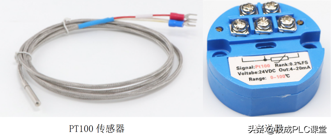
Figure 3-5-3 Temperature transmitter and sensor
(3) Transmitter type and wiring
The transmitter is divided into four-wire, three-wire and two-wire wiring methods. The "wire system" discussed here is distinguished by whether the sensor or instrument transmitter requires an external power supply, rather than how many wires the module requires or how many output signal wires the transmitter has. The following introduces the wiring method of the three-wire voltage transmitter as shown in Figure 3-5-4:
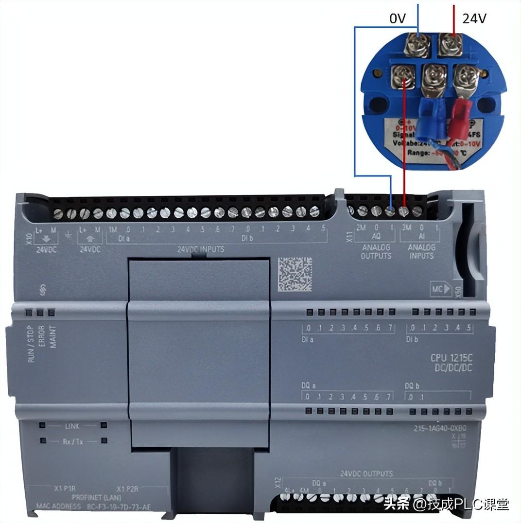
Figure 3-5-4 Temperature transmitter wiring
03. Conversion between analog and digital quantities
In actual engineering projects, readers often collect signals such as temperature, pressure, flow, etc. , so how to deal with these analog signals in the program? In other words, what is the purpose of writing an analog program? The purpose of writing an analog quantity program is to convert analog quantities into corresponding digital quantities, and finally convert digital quantities into engineering quantities (physical quantities).
The conversion of analog quantities into engineering quantities is divided into two types: unipolar and bipolar. . The bipolar -27648 corresponds to the minimum value of the engineering quantity, and 27648 corresponds to the maximum value of the engineering quantity.
Unipolar analog quantities are divided into two types, namely 4-20mA and 0- 10V, 0-20mA.
(1) The first one is 4-20mA, with offset of.
Because 4mA is 20% of the total amount, and 20mA is converted into a digital amount of 27648 , so the digital quantity corresponding to 4mA is 5530. The conversion of analog quantities into digital quantities is completed by S7-1200PLC, and readers must convert these values into engineering quantities in the program.
(2) The second one has no offset
There are analog quantities without offset such as 0-10V, 0-20mA, etc. , 27648 corresponds to the maximum engineering quantity, and 0 corresponds to the minimum engineering quantity.
(3) Analog signal (0-10V, 0-5V or 0- 20mA)In the S7-1200PLC CPU, it is represented by a numerical value of 0-27648 (4-20mA corresponds to 5530-27648 ), there is a certain mathematical relationship between the two, as shown in Figure 3-5-5
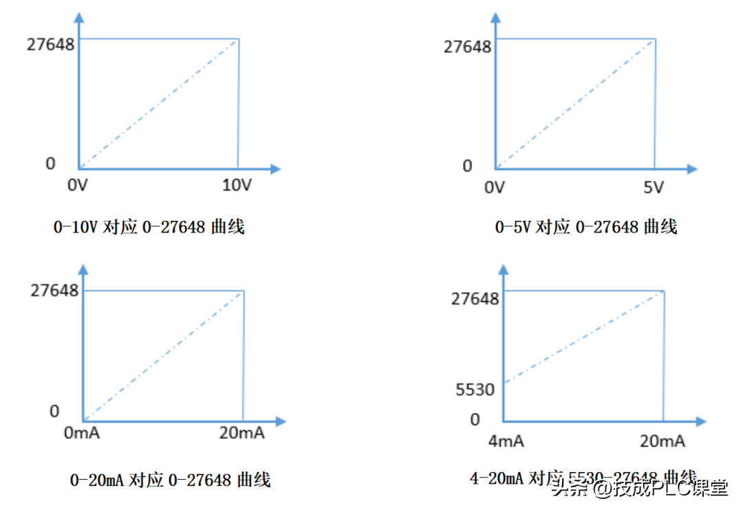
Figure 3-5-5 Analog signal and digital curve
04. Standardization instructions and scaling instructions< /strong>
(1) Standardized instructions (NORM_X)
NORM_X command: Use the "NORM_X" command to input the value of the variable in VALUE Map to a linear scale to normalize it. Use the parameters MIN and MAX to define the limits of the input VALUE value range:
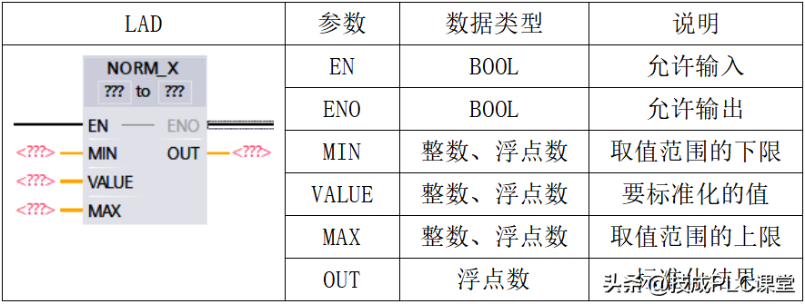
Note: You can select from the command box "<???>" drop-down list Select the data type of the instruction.
The calculation formula for standardized instructions is: OUT= (VALUE - MIN) / (MAX - MIN), where (0.0 <= OUT <= 1.0), the calculation principle is shown in Figure 3-5-6
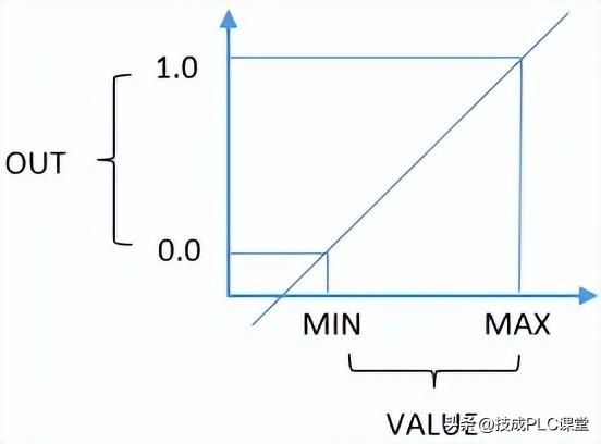
Figure 3-5-6 Calculation principle diagram corresponding to standardized instruction formulas
Use an example to illustrate the use of standardized instructions (NORM_X), the ladder diagram is shown in the figure As shown in 3-5-7:
When I0.0 is closed to activate the normalization command, the VALUE to be normalized is stored in MW10 , the range of VALUE is 0-27648, and the output range of normalizing VALUE is 0.0-1.0. Assuming that MW10 is 13824, then the normalized result in MD12 is 0.5.

Figure 3-5-7 Example of standardized instructions
(2) Scaling command (SCALE_X)
SCALE_X command: Use the "SCALE_X" command to map the value of the input VALUE to Scale it to a specified value range. When the scaling command is executed, the floating point value input VALUE will be scaled to the value range defined by the parameters MIN and MAX. The scaling result is an integer and is stored in the OUT output. The zoom command parameters are shown in the table below:

Note: You can select the command box from the "<???>" drop-down list Select the data type of the instruction.
The calculation formula of the scaling command is: OUT= VALUE (MAX - MIN) + MIN , where (0.0 <= VALUE <= 1.0), the calculation principle is shown in Figure 3-5-8;
Use an example to illustrate the use of standardized instructions (NORM_X), the ladder diagram is shown in the figure As shown in 3-5-8, when I0.0 is closed to activate the normalization command, the VALUE to be normalized is stored in MD16. The range of VALUE is 0-27648, and the output range of normalizing VALUE is 0-27648. Assuming that MD10 is 0.5, the normalized result in MW20 is 13824.
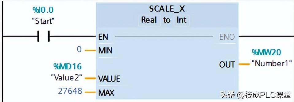
Figure 3-5-8 Zoom command example
4. Task implementation
The implementation steps of this task are mainly divided into PLC wiring, IO address allocation and program design Idea:
01. IO address allocation
| < p data-track="164">Enter address | Description | Temperature display address | Description |
IW64 | Analog input | MD24 | Temperature display |
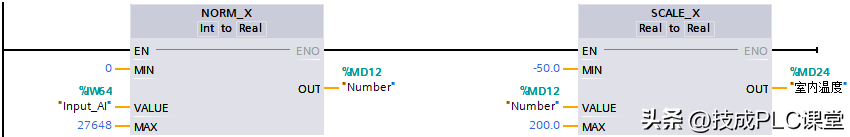
02. Programming ideas
1) Use the standardization command to standardize the collected analog values. Standardize The final range value is between 0.0-1.0.
2) Then use the scaling command to scale the standardized values. The range value is between the temperature sensor range (-50.0-200.0℃).
03. Programming
5. Experience and summary
1. The conversion of analog quantities is mainly to understand the difference between analog quantities and digital quantities. relationship between.
2. In this task, the normalization and scaling instructions are mainly used for simulation Quantity collection and conversion. When converting, pay attention to filling in the numerical quantities and engineering quantity values to avoid conversion errors.
3. In the above example, the temperature sensor range is -50℃-200 ℃, so the value needs to be filled in correctly in the scaling command.
4. If there are multiple temperature sensors on site, you can use a subroutine with parameters. It is more convenient to write in this way.
5. If the on-site sensor outputs 4-20mA current, then after standardization The value filled in for the MIN pin in the instruction should be 5530, not 0.
(Original by Jicheng Training Network, author: Guo Biao, no reproduction without authorization, violators will be prosecuted)
Editor’s recommendation:
Mobile version of electrician's calculator, quickly complete complex electrician calculations in 1 minute
6 super practical electrical calculation software that requires no installation and is worth downloading
Articles are uploaded by users and are for non-commercial browsing only. Posted by: Lomu, please indicate the source: https://www.daogebangong.com/en/articles/detail/xi-men-zi-1200PLC-mo-ni-liang-ce-wen-an-li-kan-wan-xin-shou-ye-hui-shi-yong-gong-neng-zhi-ling.html
 支付宝扫一扫
评论列表(196条)
测试