Some time ago (very long time ago, around 2013) I bought a Texas Instruments color graphing calculator TI-Nspire CX CAS from Xobao.com. I took it apart and took a look and took some photos for your reference.
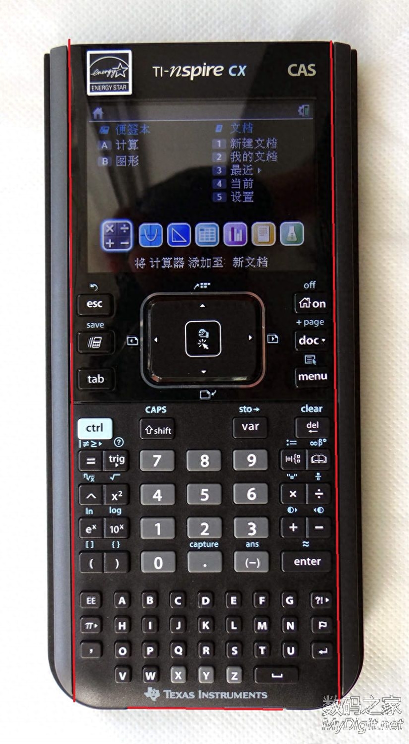
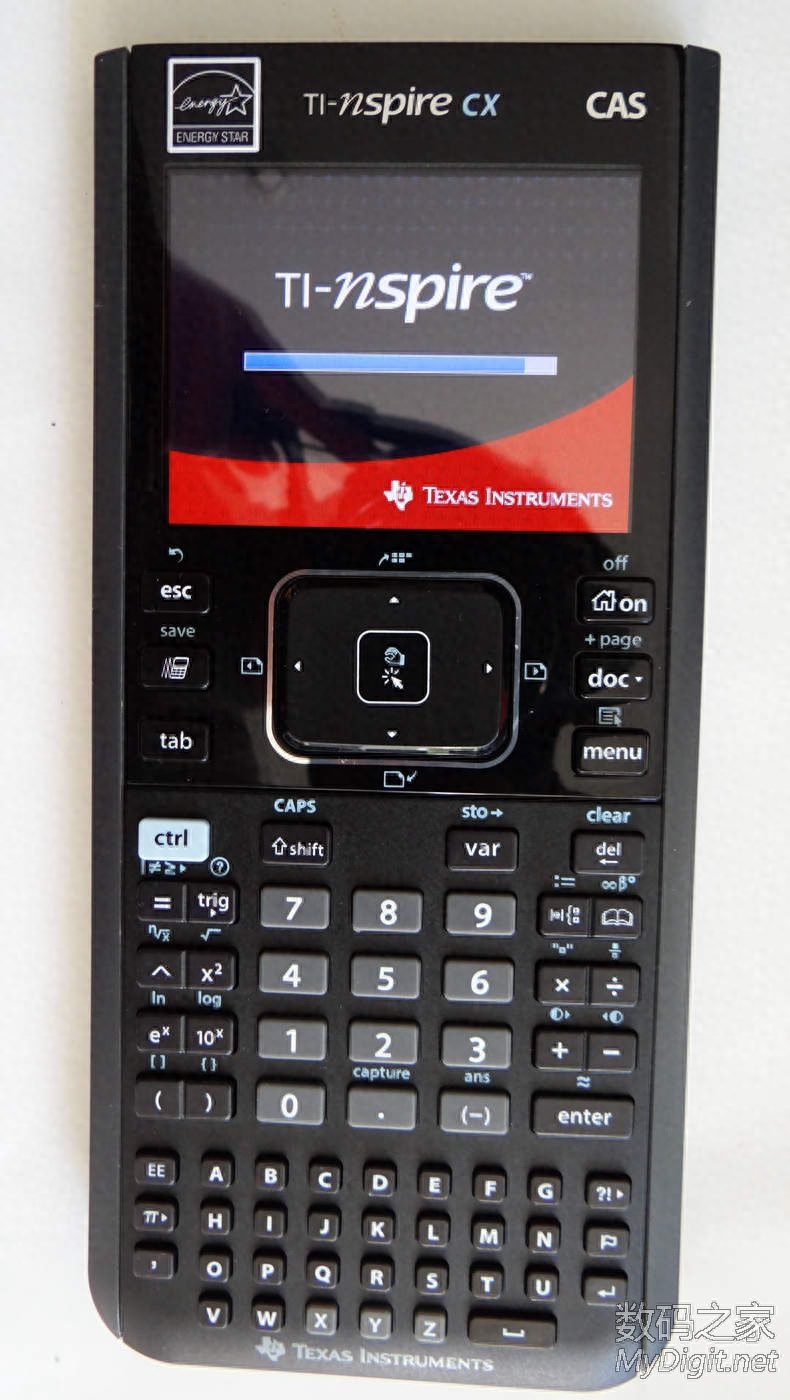
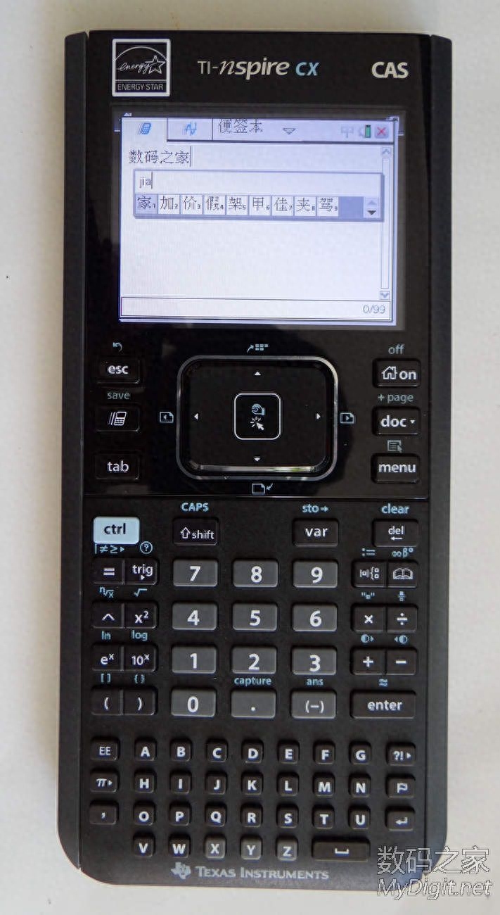
First, let’s take a photo of the front before disassembly (please ignore the “Energy Star” logo in the photo, the original machine does not have it, you can put it on yourself after you buy it):
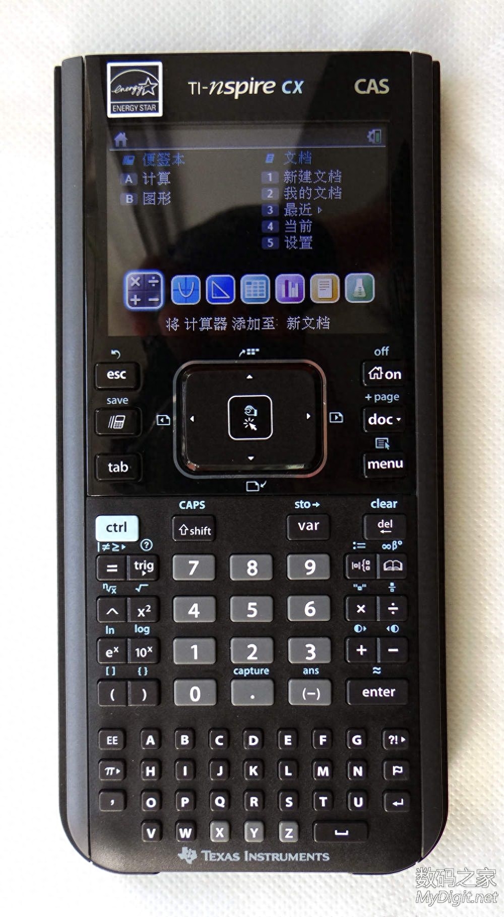
Main technical specifications of the TI-Nspire CX CAS graphing calculator quoted from the official website:
- Display size: 320 x 240 pixels (3.2 inches);
- Display resolution: 125 DPI; 16 levels of color;
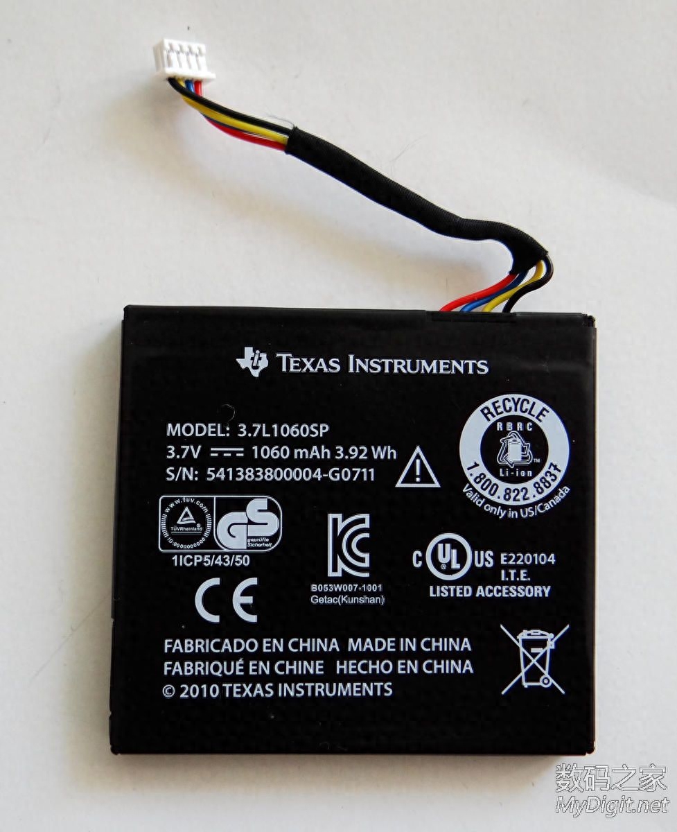
- Battery : TI-Nspire rechargeable battery (built-in);
- Memory: 128 MB storage memory / 64MB operating memory;
- USB interface: used to connect to a computer and TI-Nspire graphing calculator connections etc.
The TI-Nspire CX CAS I bought is not brand new. It is actually more than 90% new (the appearance is very close to brand new), and it cost ¥500. Brand new ones cost about ¥1200.
Preparation tools before disassembly:
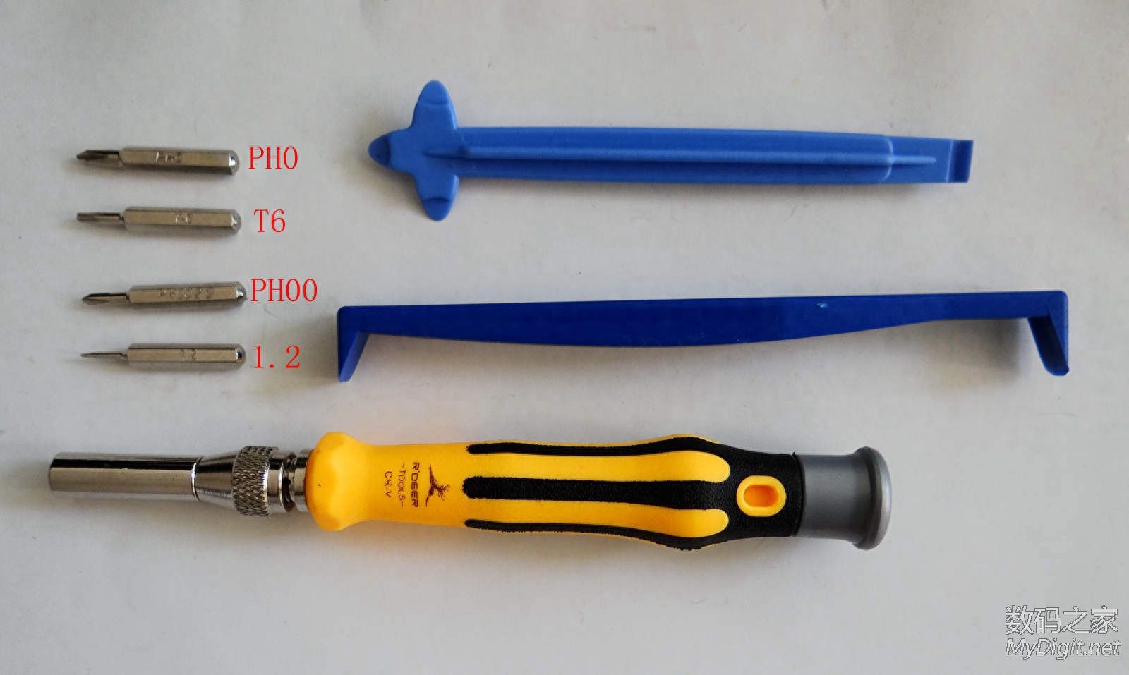
The main disassembly tools are screwdrivers and disassembly sticks. Screwdrivers require bits with the following designations: PH0, PH00, T6 and 1.2.
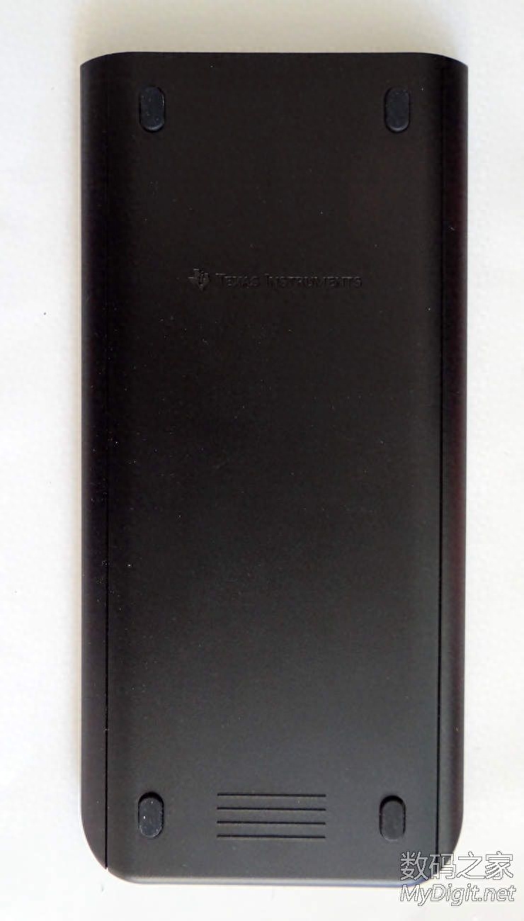
Let’s start disassembling the machine. Starting from the back (as shown in the picture below):
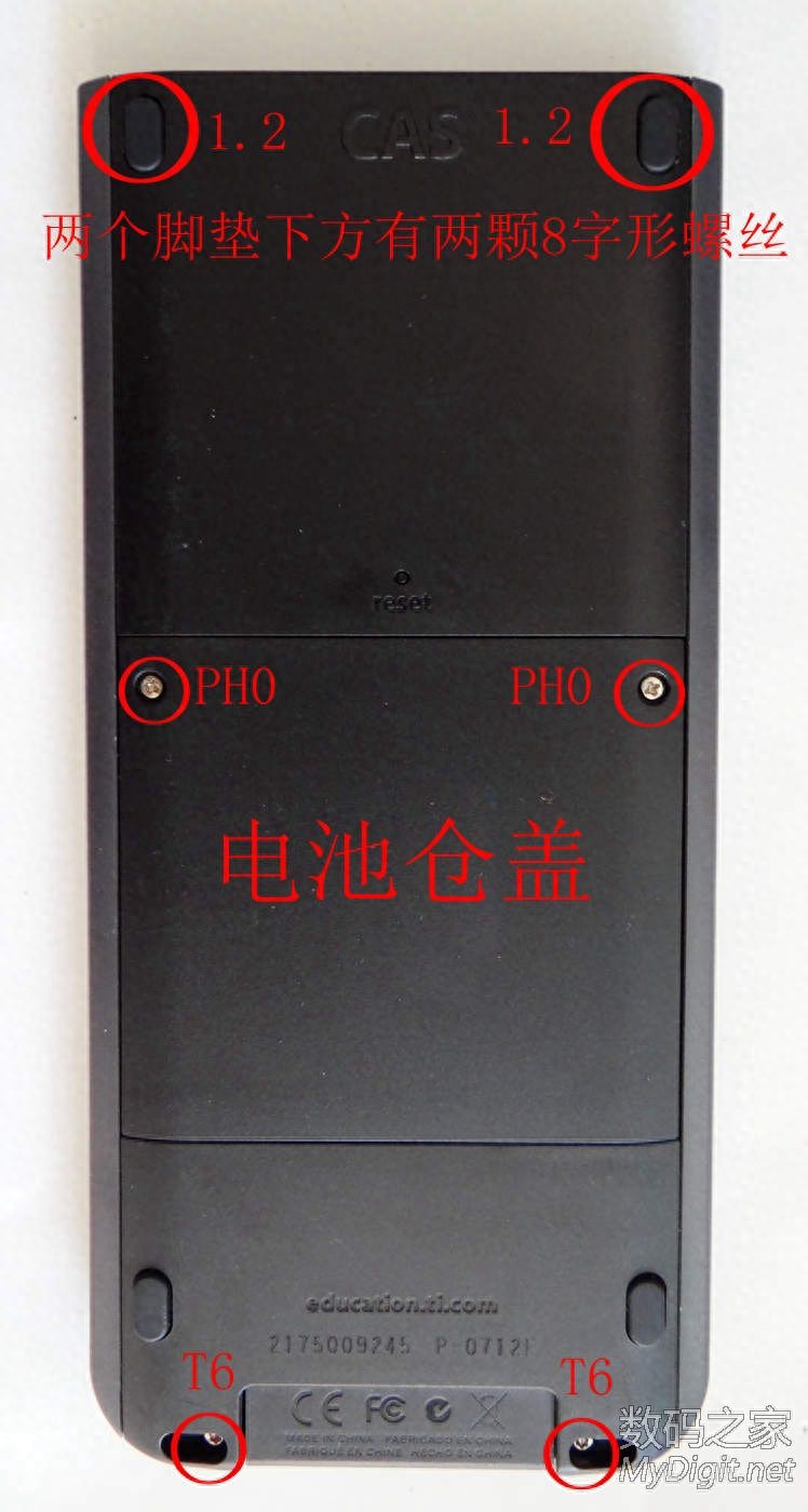
First use a PH0 screwdriver bit to remove the battery compartment cover and take out the built-in rechargeable lithium-ion battery. The photo of the back of the calculator after removing the battery compartment cover and taking out the battery is as follows:
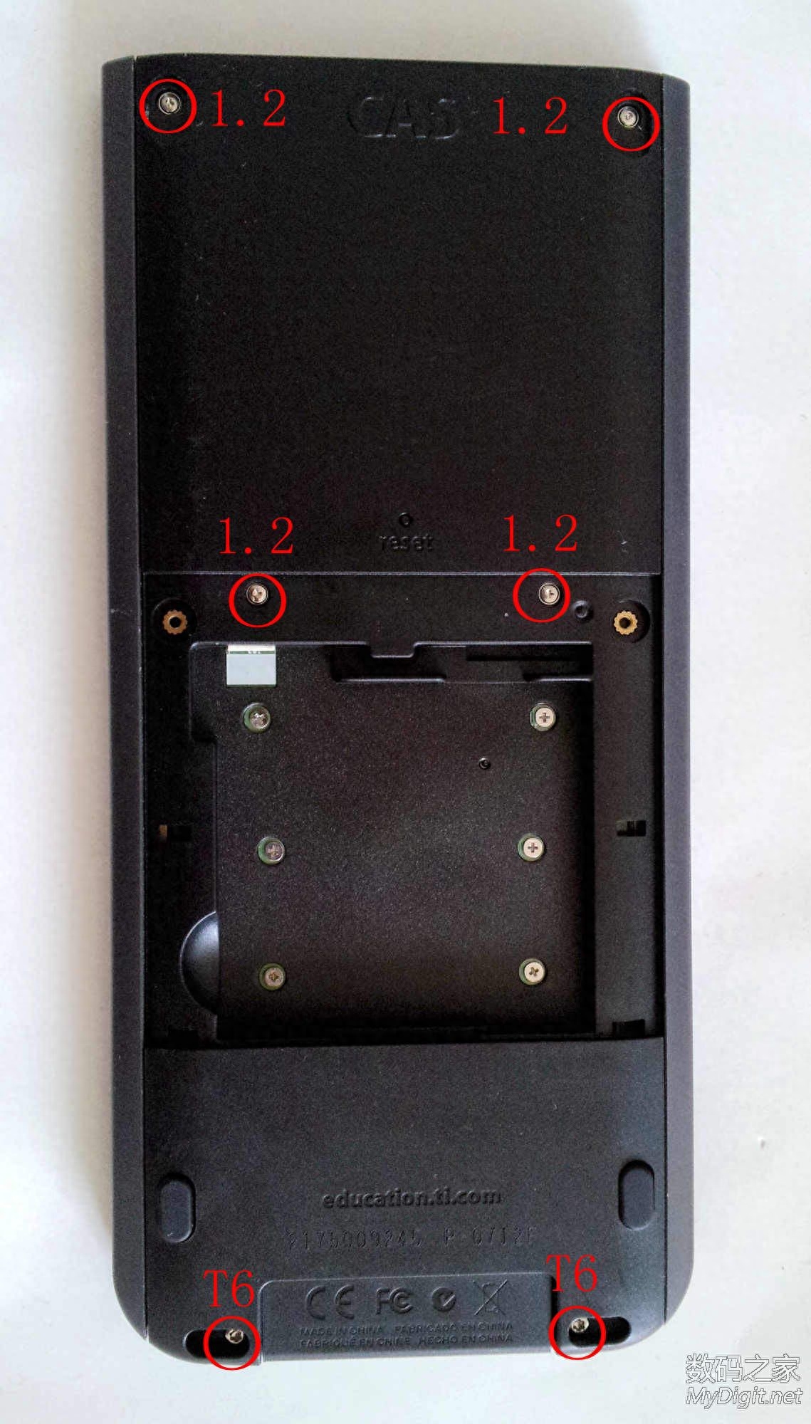
Then use a T6 screwdriver bit to remove the two torx-shaped screws at the bottom of the back; then pry open the two rubber feet at the top of the back. There are two 8-shaped screws hidden underneath, which can be removed with a No. 1.2 flat-shaped screwdriver bit; the battery compartment There are also two figure 8 screws at the top inside, which can be removed with a No. 1.2 slotted screwdriver bit. After removing the 6 screws marked in the red circle in the photo above, you can separate the back cover (see instructions below for details).
Previous photo of the built-in battery taken out of the battery compartment (lithium-ion rechargeable battery, 3.7V 1060mAh):
After completing the above steps, use a disassembly stick to separate the front panel and rear shell from the thin slits on both sides of the front of the calculator (marked by the red line in the picture below). You can separate it from the bottom of the calculator first, and then separate the thin slits on both sides from the bottom to the top. Note that the front panel is connected to the circuit board and screen at the back and must be taken out together when separated; the back shell is separable separately.
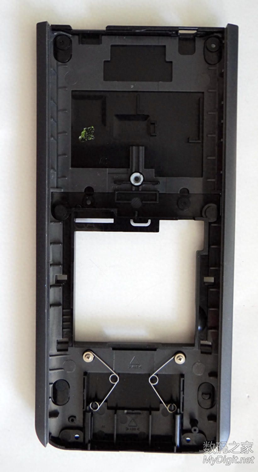
The picture below is a photo of the inside of the back case of the calculator after the front panel and internal circuit board and screen have been separated and removed:
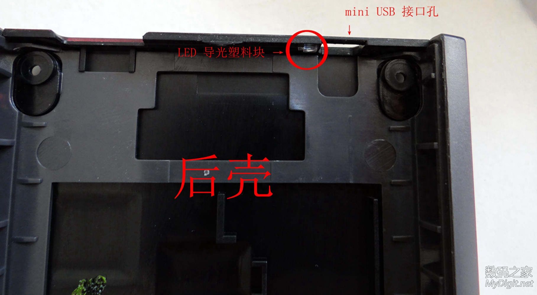
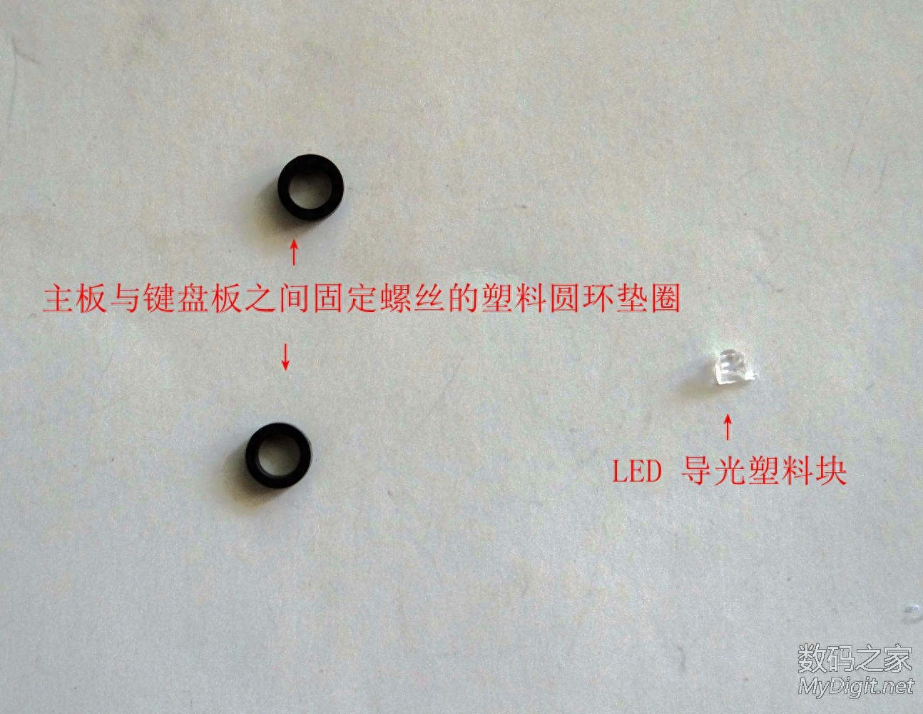
Note that there is a small plastic part next to the mini USB interface hole on the top right side of the inside of the back case (as shown below). Be careful not to lose it when disassembling the phone. This is an LED light guide plastic block that can be removed.
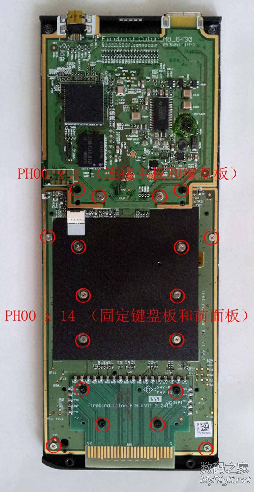
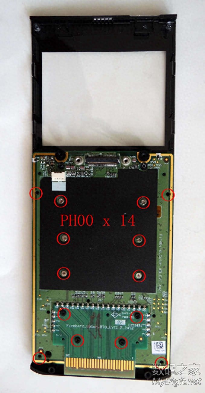
The picture below shows the back of the internal circuit board after removing the back case. The circuit board is divided into two PCBs: the motherboard in the upper half and the keyboard board in the lower half. There is a screen behind the motherboard, a rubber keyboard and keyboard buttons behind the keyboard board; and below that is the front panel. The motherboard and keyboard board are connected by a socket. After removing the 4 PH00 screws (two black and the other two white) at the bottom of the motherboard, the motherboard and keyboard board can be separated; there are 14 PH00 screws between the keyboard board and the front panel. Connect (4 black and 10 white) (all PH00 screws are marked with red circles in the picture below).
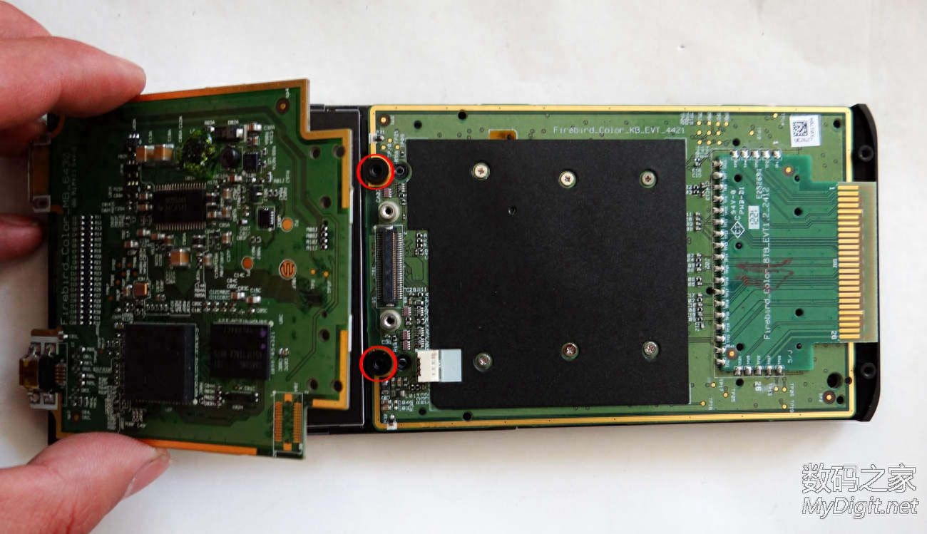
Remove the 4 PH00 screws that secure the motherboard and keyboard board, and then use the disassembly stick to separate the motherboard and keyboard board (as shown in the picture below). Note that the motherboard and the screen below are connected by a cable. When removing the motherboard, take it out together with the screen. There are two plastic ring gaskets on the top of the keyboard board that can be removed. Make sure to remember their positions so as not to lose them (as shown by the red circles in the picture below):
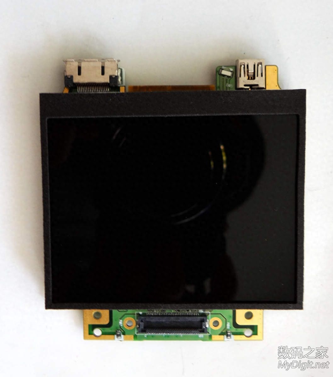
The following is the removed motherboard and screen (the two are connected by a cable):
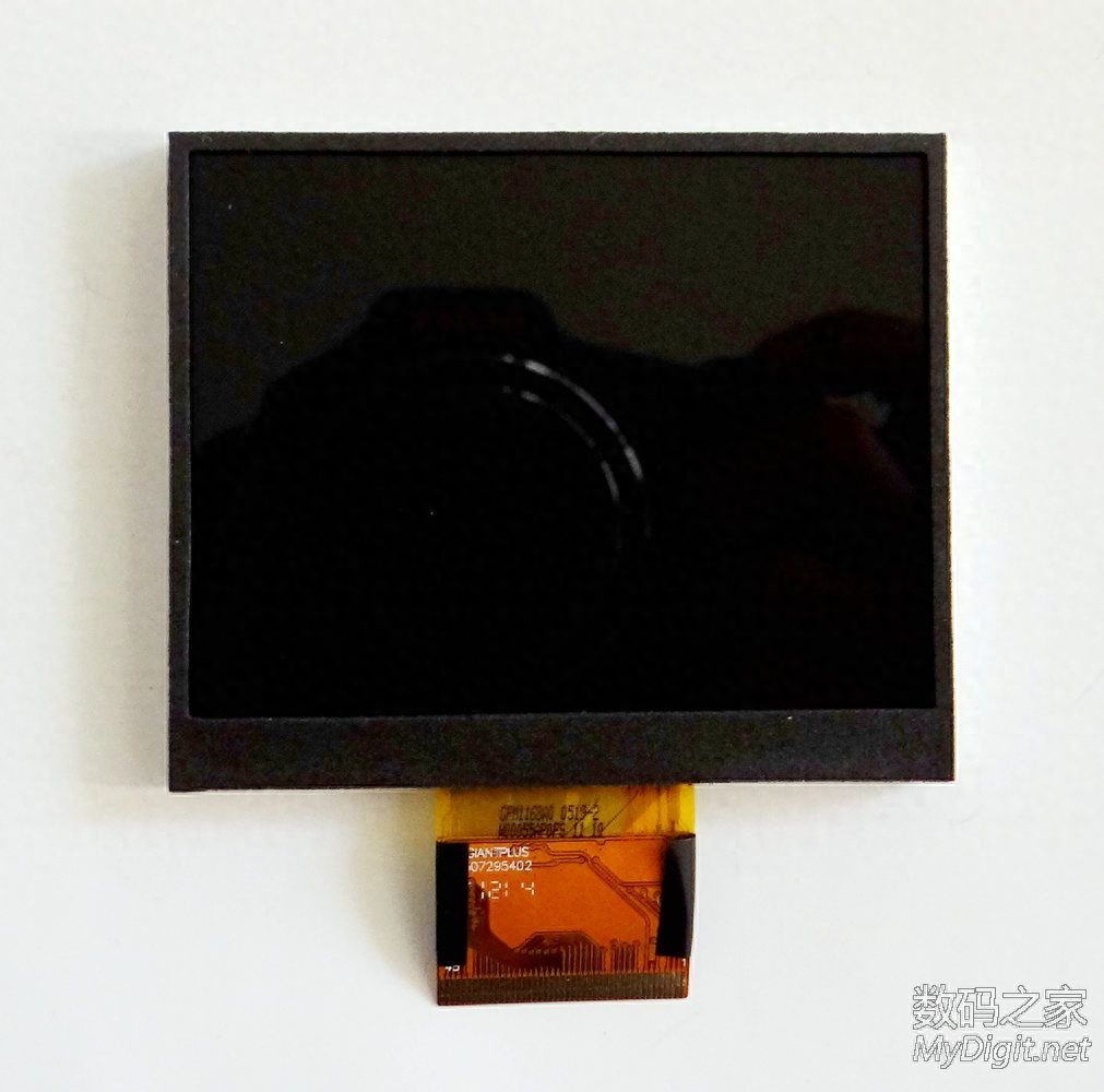
Loosen the plastic clip of the motherboard cable socket to remove the screen (as shown in the picture below). It can be seen from the text on the screen line that this screen is produced by Taiwan's Lingju Technology Company. According to the screen display effect, it is estimated that it is a 16-bit color LCD made of TFT material, 65,000 colors; the resolution is 320 x 240 pixels, 125DPI; the diagonal size is 3.2 inches; with backlight.
Remove the inside of the front panel and keyboard board after removing the motherboard and screen (as shown in the picture below). Remove the 14 PH00 screws marked in red circles in the picture below to remove the keyboard board (4 have been removed in the picture below). Note that the keyboard board must be taken out together with the rubber keyboard and four-way navigation touchpad below it, because there are cable connections between them.
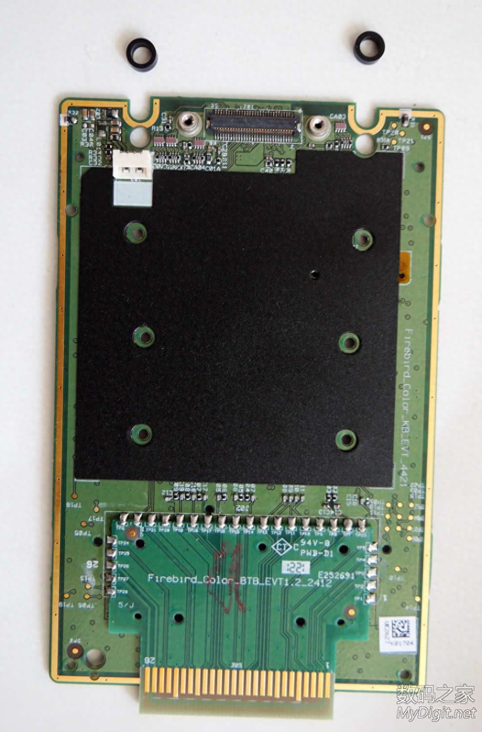
The picture below shows the keyboard board that has been removed, with a rubber keyboard and four-way navigation trackpad behind it. Note that the two plastic ring washers in the picture should be retained.
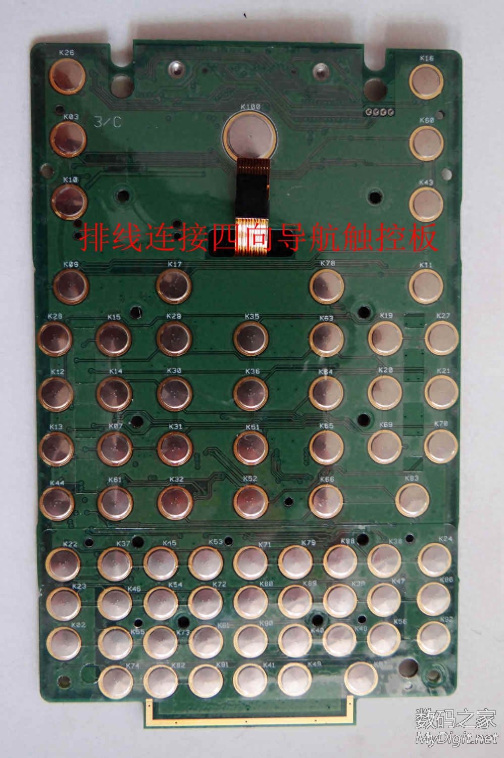
Keyboard board front view (shown below). There is a cable connection between the four-way navigation touchpad and the keyboard board. Loosen the cable clip (on the back of the four-way navigation touchpad) to separate them.
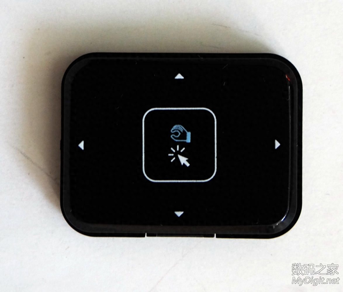
Front view of the four-way navigation touchpad removed (shown below). This can be used as the arrow keys to move in the menu, or as the mouse to move the screen cursor.
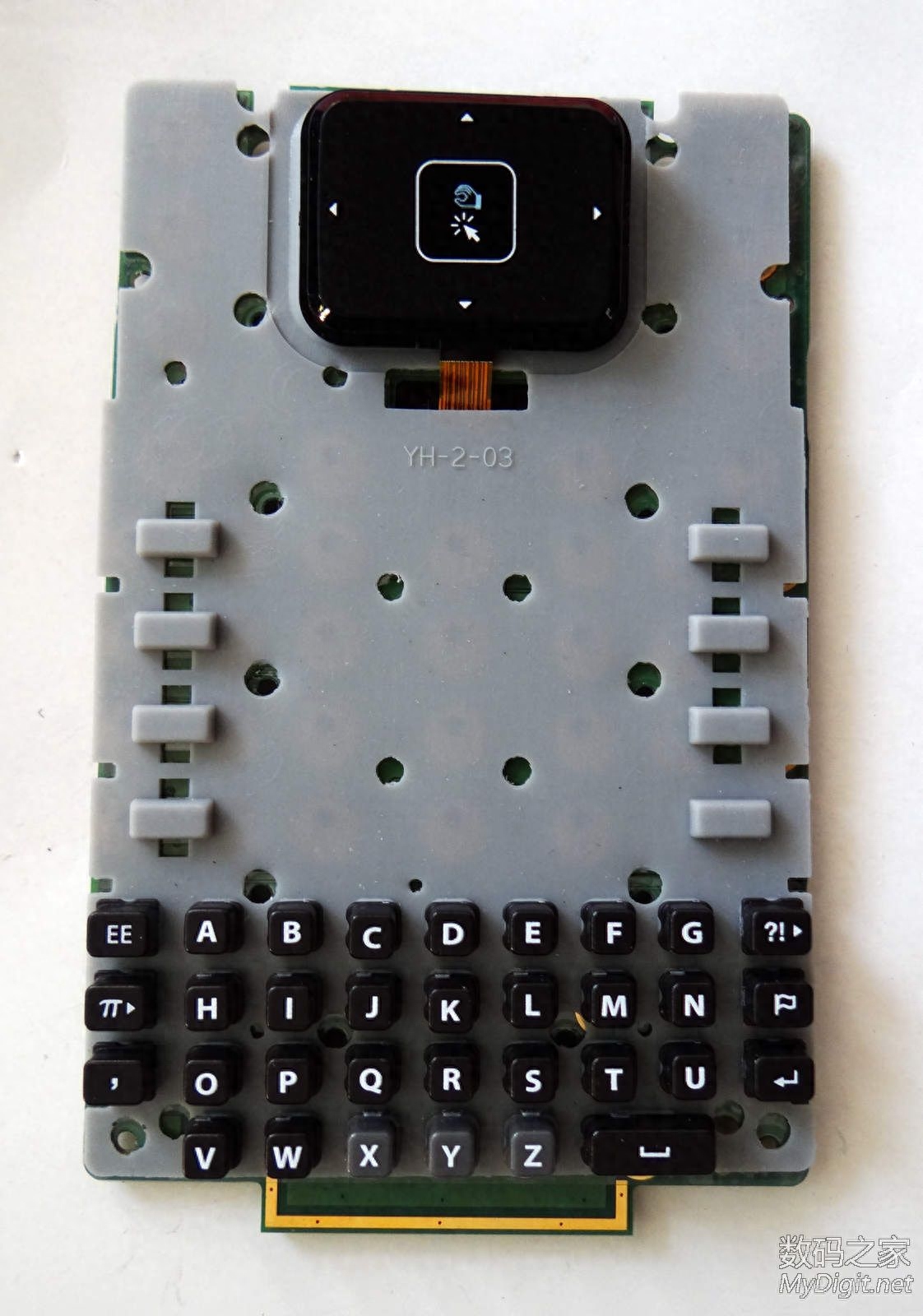
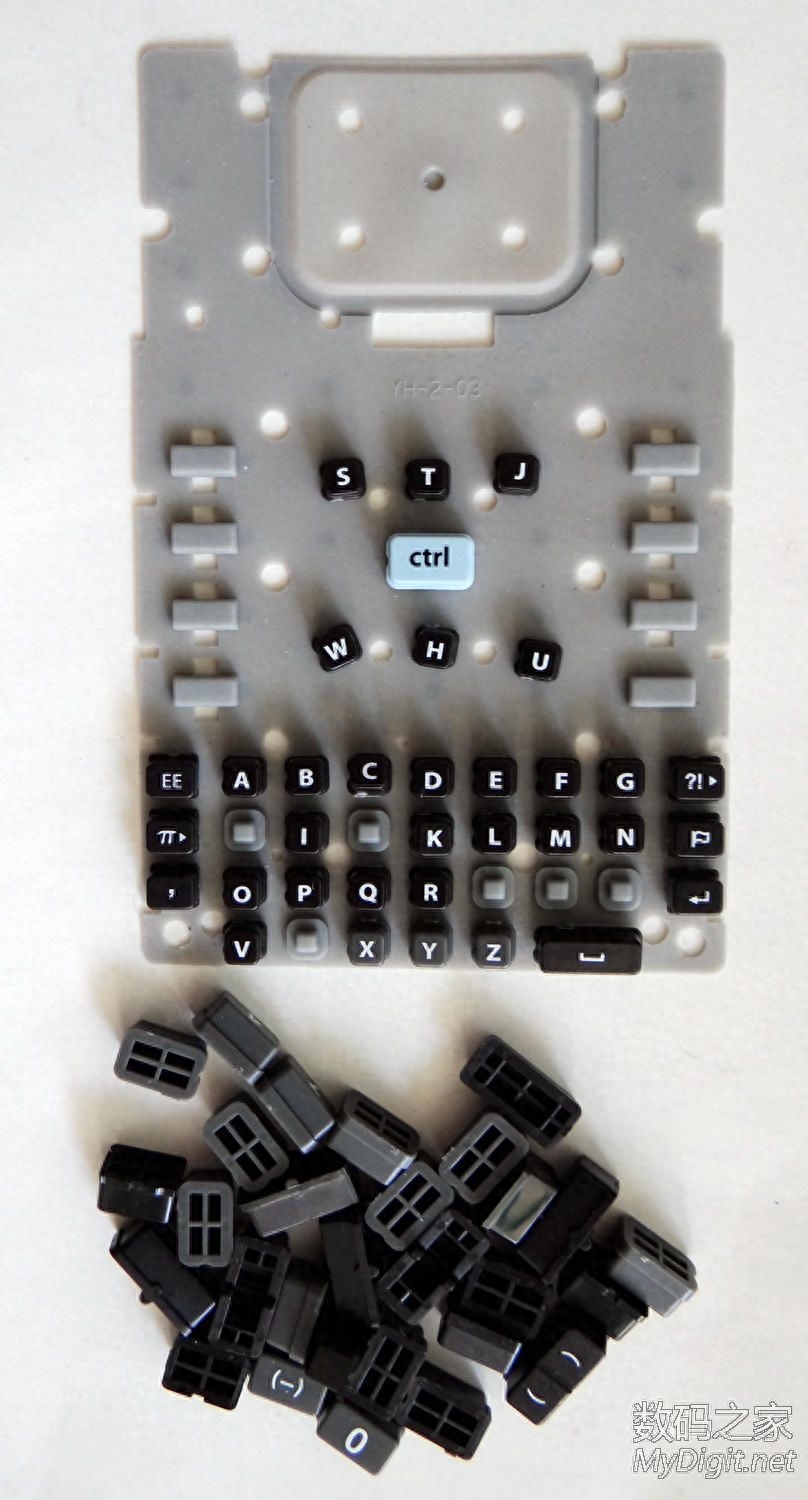
The rubber keyboard after being separated from the keyboard board (as shown in the picture below). The plastic keyboard keys above are all individually detachable. In order to adapt to the regulations of the relevant examinations in the United States, the full keyboard keys of this keyboard are arranged in alphabetical order instead of the QWERT keyboard (because calculators with QWERT keyboard cannot be used in the relevant examinations).
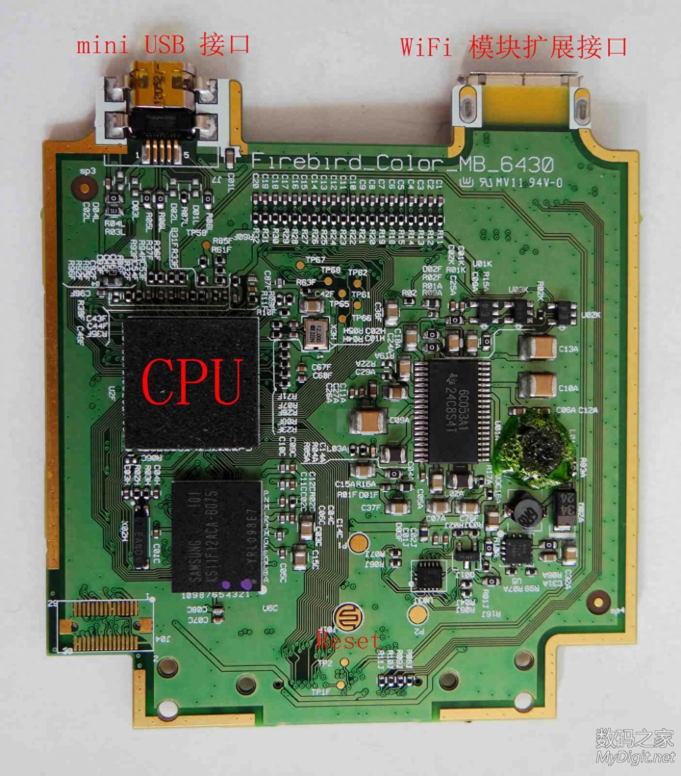
Below is the back of the motherboard of the TI-Nspire CX CAS graphing calculator. CPU: Texas Instruments ARM architecture, clocked at 132 MHz (there is a rubber pad on the CPU, but it is not peeled off to see the specific model because it is very tight); Memory: 64MB RAM, 128MB Flash ROM. There is a mini USB interface on the top of the motherboard for connecting to a computer and other TI-Nspire calculators. It can be used to transfer data and can also be connected to a USB charger for charging. There is also a WiFi module expansion interface. After plugging in the dedicated wireless module of the TI-Nspire CX series, you can connect to the classroom's dedicated WiFi network to upload and download homework files.
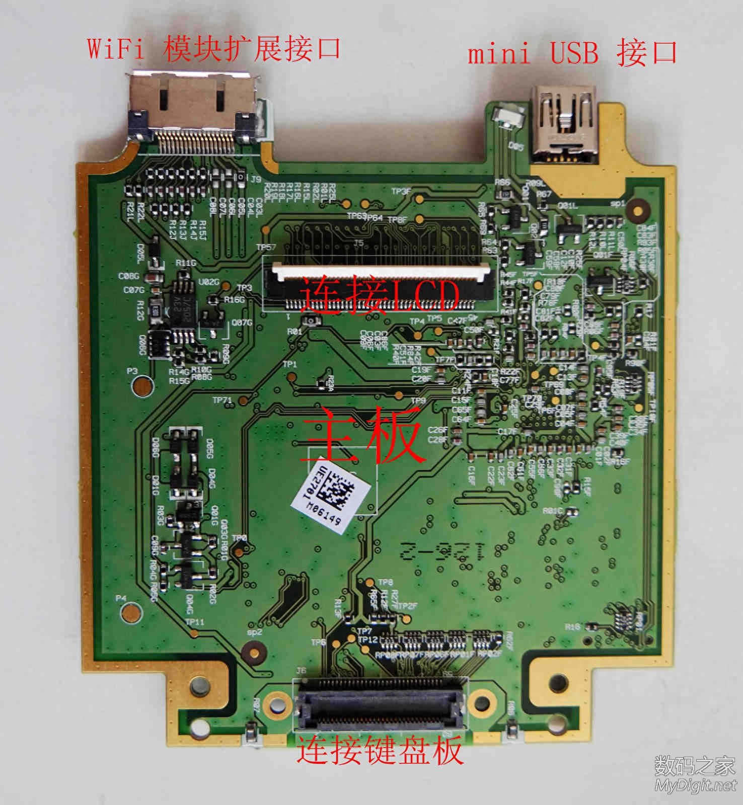
Below is the front of the motherboard of the TI-Nspire CX CAS calculator. The upper part has a socket for connecting the screen cable, and the lower part has a socket for connecting the keyboard board.
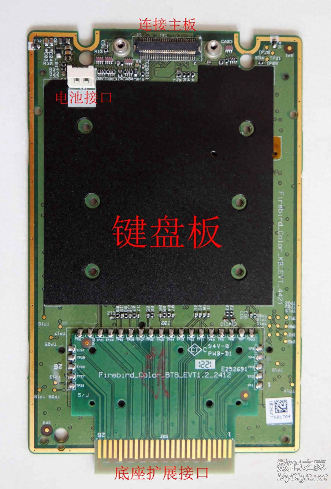
Below is the back of the keyboard deck of the TI-Nspire CX CAS calculator. There are socket interfaces, battery interfaces and base expansion interfaces for connecting to the motherboard (which can be used to connect to TI's special experimental base to collect experimental data such as rate and temperature in real time).
Below is the front of the keyboard deck of the TI-Nspire CX CAS calculator. There is a cable connected to the four-way navigation touchpad (already removed).
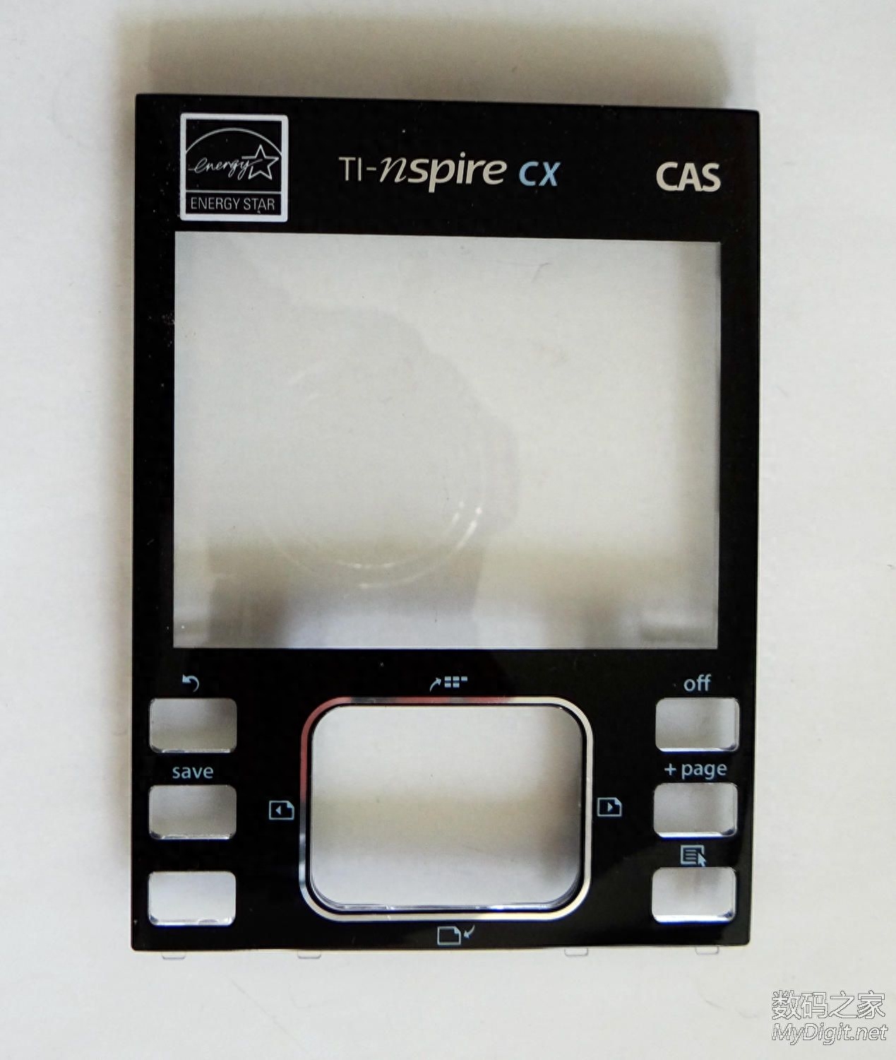
Below is the upper half of the front panel, which is the front panel of the screen. This kind of plastic material is brighter, but more prone to scratches.
Below is the lower half of the front panel, which is the front panel of the keyboard.

The following are separated independent widgets. When putting it back, remember to put it in its original position.
The disassembly is now complete. When putting it back together, just follow the reverse steps of the disassembly process, so I won’t go into details here. The following is the power-up picture after reassembly (the calculator is loading the TI-Nspire CX CAS operating system):
Text input interface (built-in Chinese Pinyin input method):
Just draw a function graph:

Finally, add a photo of the calculator’s protective case:
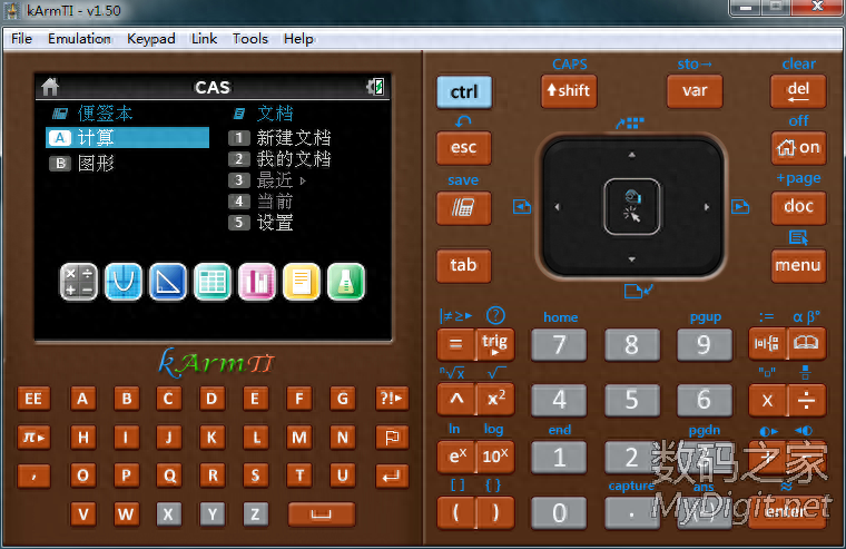
Friends who are interested in this calculator can try to install an emulator on their computer and load the ROM officially provided by TI. The running effect in the emulator is exactly the same as that of the actual machine. The following is a computer (Windows system) ) simulator - screenshot of the main interface of kArmTI 1.50 (loading TI-Nspire CX CAS 3.6 system ROM, the simulator has a variety of skin interfaces that can be replaced):
Thanks for watching!
Follow the Digital Home website to browse more exciting information, disassembly pictures and DIY DIY
For technical exchanges, please contact the original author
Author:stj2002
Source of this article: Digital Home
Articles are uploaded by users and are for non-commercial browsing only. Posted by: Lomu, please indicate the source: https://www.daogebangong.com/en/articles/detail/neng-da-zi-hua-tu-de-cai-se-tu-xing-ji-suan-qi-chai-jie-de-zhou-yi-qi-TINspire-CX-CAS.html
 支付宝扫一扫
评论列表(196条)
测试