
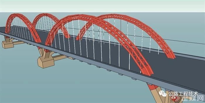
1. The two-way four-lane expressway standard with a design speed of 80Km/h is adopted. The width of the integral roadbed is 24.5m. The standard section of the bridge is shown in the figure below:

2. The design load level of main line bridges and culverts: Highway-I level;
The road to be handed over (expressway and first-class highway: highway-class I, second-class road and third- and fourth-class roads: highway-class II; below class four: highway-class II multiplied by 0.6 to 0.8 coefficient) .
3. Earthquake action: the peak acceleration of the earthquake is 0.05g.
4. Design flood frequency: 1/300 for extra large bridges, 1/100 for large, medium and small bridges and culverts.
5. Considering the possibility of implementing the maintenance cover and the traffic safety of some special super-high vehicles in the future, and considering the requirements of construction clearance, the clearance height of bridges crossing county roads (including county roads) and above grades should be increased to 5.5 as much as possible m, marked as 5.5 m; cement roads and country roads marked as 5.0 m, and other marked as 4.5 m.


1. General diagram of the superstructure of the main line bridge (including quantity table, standard cross-section, general structure diagram, beam layout)
20m prestressed concrete small box girder (integral subgrade 0°, 15°, 30°)
25m prestressed concrete small box girder (integral subgrade 0°, 15°, 30°)
30m prestressed concrete small box girder (integral subgrade 0°, 15°, 30°)
40m prestressed concrete small box girder (integral subgrade 0°)
For specific drawings, please refer to the general drawings of the superstructure of each span
2. General diagram of the substructure of the bridge on the main line (corresponding to the general diagram of the superstructure of the bridge on the main line)
Prestressed concrete split small box girder (including general structure diagram of 20, 25, 30m, 40m span abutment and bridge pier)
3. General map of culverts
ф1.5m reinforced concrete circular pipe culvert (0°~45°, 5° level 1)
2.0, 4.0, 6.0m reinforced concrete cover culvert (0°~45°, 5° level 1)
2.0, 4.0, 6.0m reinforced concrete box culvert (0°~45°, 5° level 1)
4. The design contents of ordinary bridges and ramp bridges include (arranged in the order of publication of drawings):
A) Quantity list of the whole bridge project
B) Bridge site plan
C) Engineering geological longitudinal section of the bridge site (the unified design of the geological survey unit, special or complex geological conditions of the bridge also need to provide engineering geological plan)
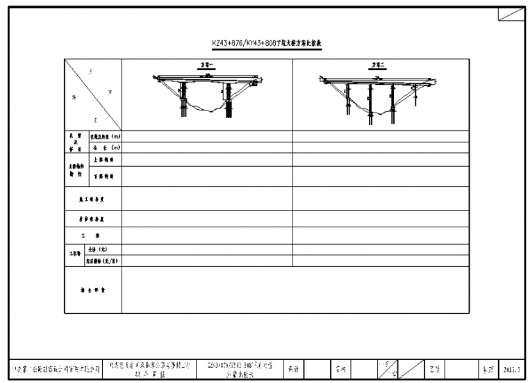
D) Comparison table of bridge schemes (general bridges do not have, bridges with comparison schemes need to be added, the specific style is as shown in the figure below)
E) Bridge type layout (horizontal and vertical data tables are drawn for the middle bridge and bridges above the middle bridge)
F) Cross-sectional view of the superstructure (mainly for the sections of prefabricated variable-width mainline bridges and interchange ramp bridges, which will not be published for standard-width bridges)
G) Construction process diagram (for special structures such as long-span variable-section box girders)
H) General structure diagram of special structure
I) Layout of steel beams for special structures
J) General structural diagram of abutments (mainly abutments for interchange ramps, abutments with widened main lines or U abutments; U abutments require the amount of concrete and the quantity of filling and excavation for each part of the structure)
K) General structure diagram of bridge piers (mainly transition piers, inter-ramp piers, and bridge piers of special structures; non-special piers of prefabricated structures will be published by the general diagram below, and will not be published for specific bridges)
5. Comparison plans (comparison plans should be drawn for both special-structure bridges and super-large bridges), which should include all the above-mentioned drawings except the "Bridge Scheme Comparison Table" at the same time;
6. For culverts and passages, only quantity tables are provided; for small bridges and overpasses, only typical style drawings and quantity tables are provided.
7. For separated overpasses, the plan, longitudinal and cross-sectional views of the bridge to be designed shall be added on the basis of the drawings required for ordinary bridges.
1. When the project is not restricted by terrain and features, the bridge span shall be carried out according to the following principles layout:
(1), average pier height H<20m, choose 20m prestressed concrete small box girder
(2), 20m≤average pier height H<25m, choose 25m prestressed concrete small box girder
(3), 25m≤average pier height H<35m, choose 30m prestressed concrete small box girder
(4), average pier height H≥35m, choose 40m prestressed concrete small box girder
There are three angles of 0°, 15°, and 30° in the general diagram of the above-mentioned small span box girder structure. In practical applications, when the structural angle is greater than 30°, the difference in slope can be accommodated by increasing the standard span.
2. The filling height of the bridge head subgrade in this project should be controlled according to the allowable post-construction settlement, and should not be higher than 10m. Generally, it can be controlled at about 8m. When the filling height of the abutment is greater than 10m, in principle, additional construction should be made Bridge, but under the premise of ensuring the stability of the abutment, the filling height of the abutment can be appropriately increased and the bridge length can be shortened. Special circumstances should be decided through consultation with the project department.
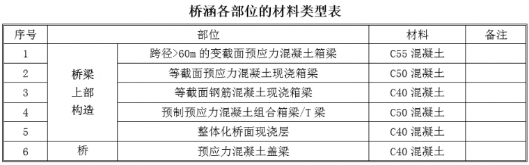
3. Environmental conditions: Class I;
4. The strength grade of concrete for this project is suggested in the following table:

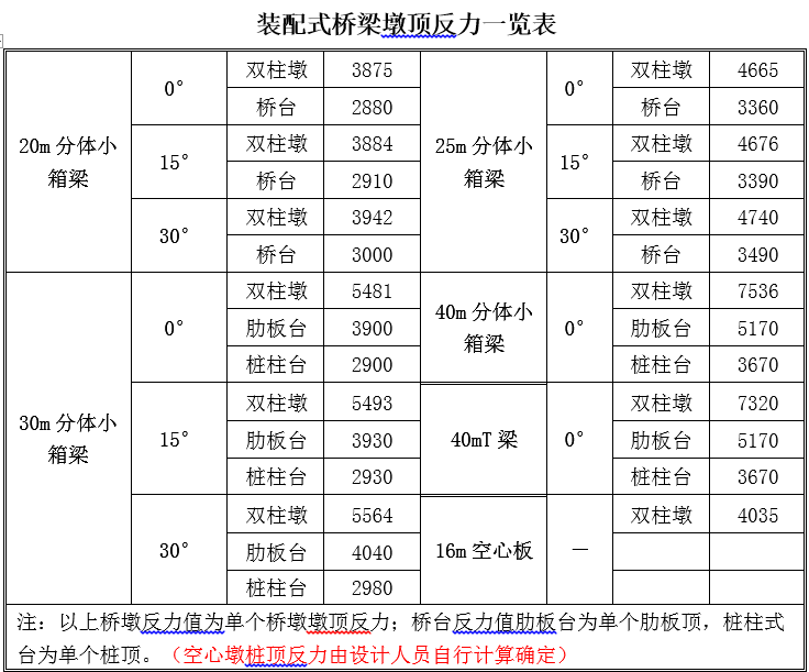
5. The length of the pile foundation must be calculated for each bridge, and the pile length calculation book should be given. The reaction force at the pier top of each span of the prefabricated structure is as follows:
6. The bridge type diagram must contain the following contents: intersecting road pile number, intersection angle, elevation, clearance before and after widening, road name, direction; mark river name, flow direction, time measurement water level, maximum navigable water level, navigation Clearance requirements and design flood level; mark the position of pipelines and optical cables; mark geological boreholes and their numbers and pile numbers, corresponding to the bearing capacity value and friction value of the soil layer; for different upper and lower structures, their section diagrams should be given; they should be drawn Schematic diagram of structural division; parameter table of pier height and pile length; elevation of pier cap and pile bottom or enlarged foundation.
The starting point and ending point of the bridge are uniformly marked. When the horizontal terrain at the bridge position is relatively gentle, only the ground line at the design line may be indicated.
The format requirements for notes in bridge layout drawings are as follows:
“Note:
1.The size of this picture is in centimeters, and the pile number and elevation are in centimeters meter meter.
2. Car Load Class: Highway—IClass (or Highway— IILevel).
3.The plane of this bridge is located in the radiusR—< strong >0000mleft /On the right-sided circular curve (on the transitional curve), the vertical plane is located atR—00000mConcave/ on a convex vertical curve (±0.00 %Single/ Two-way slope).
4.The superstructure of this bridge adopts00mPrestressed concrete split small box girder (< /em>Tbeam), simply supported/Simplified support first and then continuous structure, the division is as follows:< /span>0×00+0×00+…; the substructure adopts double-column piers, bored pile foundations, piles (rib) type abutment, enlarged foundation.
5.The inner guardrail of this bridge is reinforced< /em>SBmlevelF type reinforced concrete wall guardrail, the outside adopts< /strong>SBgrade reinforced concrete wall guardrail . [ ]m Long board.
6.This bridge uses< /strong>GYZ/GPZsupport, please refer to the structure for specific modelsSchematic diagram of the branch.
7.This bridge uses< /strong>D80( D160) The modular expansion joints have a total of ×× channels, respectively located in 0#Taiwan, 3#Tunhe< em >5#Taiwan.
8.This bridge crosses the ×× River and[S113]Dart road, please refer to the specific intersection angle and cross stake number The floor plan shows that the ×× River[is × level fairway, clearance requirementsa× bm]No navigable requirements.
9. (with other special instructions). "
< /section>
1. Abutment: Rib abutment, seat abutment or pile abutment, pile foundation. The abutment filling height H ≤ 4.5m should adopt column type abutment; H > 4.5m can adopt rib type abutment or seat plate abutment. The slope ratio of the front cone slope along the road direction of the rib-plate abutment, slab-type abutment or pile-column abutment should be 1:1.5.
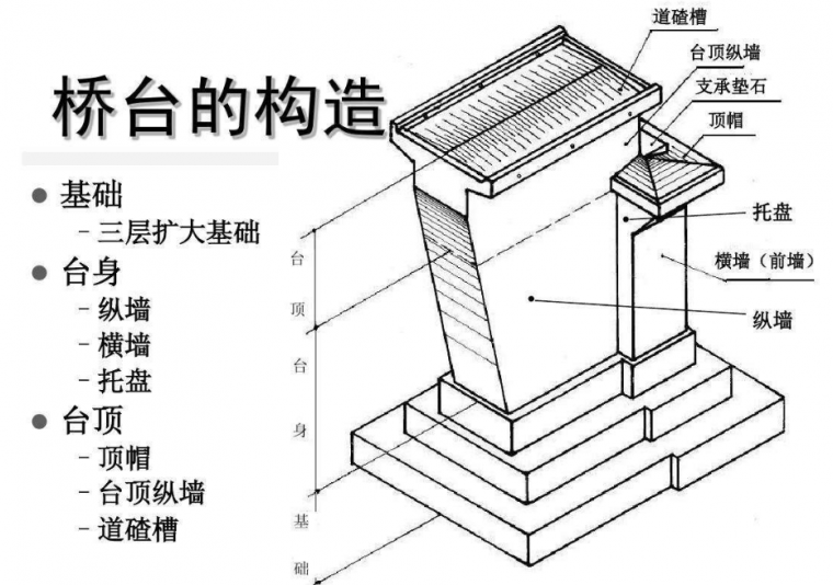
2. Pile-type, cap-separated, and rib-plate abutment earwalls are set on the inner side of the bridge width, with a thickness of 50cm; When the diameter is 25m, take 3m, and the tail wall height is 75cm; when the span is 30m small box girder, take 3.2m, and the tail wall height is 75cm; when the span is 30m T beam, take 3.5m, and the tail wall height is 75cm; when the span When it is 40m, take 4m, and the height of the tail wall is 75cm.
3. Bridge piers: pile-based double-column piers and expanded foundation double-column piers are used when the pier height is less than 35m; pile-based rectangular cross-section double-column piers can be used when the pier height is less than 35m and less than 50m. Considering the convenience of construction and the beauty of the bridge, the types of piers in different forms should be reduced as much as possible.

4. Please refer to the general drawing of the substructure of prefabricated bridges for specific dimensions of circular and rectangular cross-section double-column piers, hollow thin-walled piers, pile-type abutments, and rib-type abutments.
1、 Bridge deck paving:
Regular Bridge
(1). From top to bottom, the first layer is "12cm asphalt concrete bridge deck pavement".
(2). The second layer is "Waterproof layer". The thickness of this layer is not counted, but the number of waterproof layers needs to be calculated in m2.
(3), the third layer is C40 concrete cast-in-place layer. The thickness of the cast-in-place layer of the prefabricated T-beam and small box girder is 10cm,
The cast-in-place layer of the large-span cast-in-place box girder takes 6cm.
2, Anti-collision facilities:
(1), the main line integrated subgrade super-large bridge, the main bridge, the middle bridge, and the small bridge are all equipped with SB grade reinforced reinforced concrete wall guardrails (outsourcing type, width50cm), the inside is SBmgradeF< /span>type reinforced concrete wall guardrail (width45cm, leave 5cmshelving width). SS grade reinforced reinforced concrete wall guardrails are used on both sides of the separated subgrade super-large bridge, large bridge, middle bridge and small bridge.
(2), both sides of interchange ramp bridges, separated overpasses and flyovers adopt SB grade reinforced reinforced concrete wall guardrails; interchange ramp bridges SBmlevelF reinforced concrete wall guardrails are used for the central divider in the design of two bridges.
(3) For bridges that span the main line, roads with heavy traffic, railways and navigable rivers (including ramp spans), anti-falling object nets should be installed on the outside of the bridge.

3, Continuous bridge deck and expansion joint setting
Both the main line bridge and the outer line bridge adopt modular expansion joints of different specifications. The principles of use are as follows:
(1). For bridges with continuous structure, set expansion joints at the abutment, and add expansion joints in the middle according to the number of holes.
(2), when the terrain of the bridge site is relatively gentle, the length of one link should be controlled as much as possible to 120m, use D80 type modular expansion joints; when the terrain is undulating, the position of the transition pier can be reasonably determined according to the actual pier height distribution. Increase or decrease the length of each bridge. The length of the largest link should not exceed 240m for bridges that adopt a simply supported structure followed by a continuous system.
(3), in principle, the main line multi-hole bridge, the span of a single hole is less than or equal to 30mAdopt simple support first and then bridge deck continuous type;30mSpan bridges generally adopt simple support first and then continuous structure or continuous rigid frame.

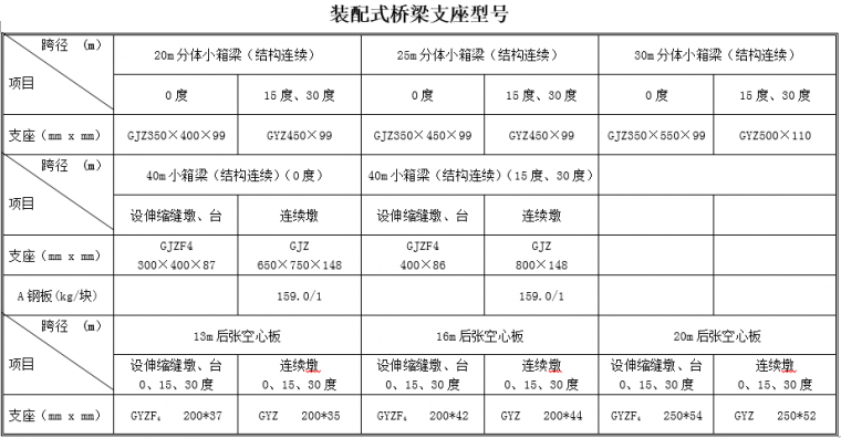
4、Bridge support
(1) For prefabricated structural supports, the requirements in the following table "Model of Prefabricated Bridge Supports" shall be adopted uniformly. For cast-in-place continuous beams or long-span bridges, basin-type rubber bearings should be used. The total height of the support system of prefabricated bridges and small-span cast-in-place bridges (from the bottom of the beam to the top of the cap beam, including the height of concrete wedges, supports, and support pads) is uniformly formulated;20m , 25m, 30mThe total height of the split small box girder support is< /span>30cm; 30m, 40m split small box The total height of the beam support is30cm.
(2),30m bridges with a span of more than 30m can be properly consolidated according to the pier height and joint length of some piers in a joint, and the others are not consolidated The middle pier can adopt basin rubber bearing. When the longitudinal slope of the bridge deck is greater than 3%, for a prefabricated bridge with a continuous structure, a consolidation pier or a fixed support pier should be installed in the middle of a bridge span to prevent expansion joints One-way running. When the longitudinal slope is greater than 2.5%, and it is not suitable for consolidation, pot rubber bearings can be used to prevent the beam from sliding down.
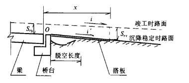
5. Bridgehead
(1). In principle, the abutments at both ends of the bridge must be provided with abutments;
(2),Designed length of abutment slab
The design length of abutment slabs for super-large bridges, large bridges, and medium bridges is;
When the filling height of the embankment at the bridgehead is ≥5m, the length of the abutment slab shall be 8m ;
When the filling height of the embankment at the bridgehead is <5m, the length of the abutment slab shall be 6m ;
Small bridges, clear culverts, and passages all use 6mlong boards.
(3) The abutment slabs of oblique bridges are designed to be stepped.The connection between the abutment and the abutment is parallel to the back wall, and the connecting subgrade end is perpendicular to the center line of the main line.
(4)、The road to be handed over spans separated overpasses and overpasses, and the length of the slab for the first- and second-class roads is 6m; there is no slab below the third-class road, and the bridge head embankment Rammed gravel.
Note: A small split box girder (simply supported first and then the bridge deck is continuous) is provided with a support at one end of a box girder.
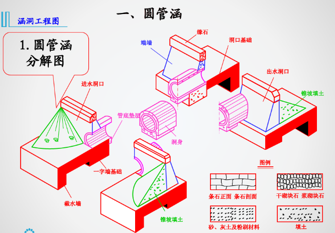
This project mainly adopts reinforced concrete cover culvert (channel) and circular pipe culvert;
1. For mountainous road sections, in principle, reinforced concrete circular pipe culverts should not be used as much as possible on the main line, and circular pipe culverts can be installed according to the actual situation in flat areas where conditions permit. In order to facilitate dredging, the minimum aperture of the culvert should not be less than 1.5m.
2. When the filling height of the top of the culvert does not exceed 12m in general road sections, reinforced concrete cover culverts are used; For a reasonable design scheme, if culverts are recommended, reinforced concrete slab culverts or concrete arch culverts can be used according to the geological conditions of the foundation, which are specially designed by each design unit.

3. In order to improve the driving conditions on the road surface, under the condition that the filling height and drainage meet the requirements, dark culverts/channels should be used as much as possible.

4. When the channel length is greater than or equal to 50m, a lighting well must be installed.
1. According to the requirements of the document legend of the Ministry of Communications, all drawings of this project shall use "note", "Notes" are not used.
2. The marked arrows are uniformly single arrows;
3. The design document adopts A3 format, and the extended A3 diagram is divided into standard A3 format for printing, so as to facilitate document publication.
4. Font: The frame uses imitation Song _GB2312, and the drawing uses FSDB and FSDB_E. Character height: height 5 for titles and section symbols, height 4 for notes and directions, height 3 for characters in tables, height 2.5 for annotations and descriptions, and 2.0 for drilling descriptions; the actual height of characters is the specified height × global ratio. Width Scale: 0.75.
5. The picture title in the picture frame is divided into upper and lower layers.
Indicate the name of the bridge on the upper layer. The general bridge with integral subgrade is: Kxxx+xxx XXX bridge (plan 1), and the bridge with staggered holes on integral subgrade is: left K11+655.5/right K11+635.5 XXX bridge (plan 1).
Indicate the name of the drawing in the lower layer: Bridge layout drawing, and the upper right corner of the drawing frame is marked as the "page number/pages in total" of the drawing.
6. For other matters that are not detailed, please submit them for discussion in time to improve this regulation and strive to unify the design documents.
Articles are uploaded by users and are for non-commercial browsing only. Posted by: Lomu, please indicate the source: https://www.daogebangong.com/en/articles/detail/What%20are%20the%20regulations%20and%20requirements%20for%20the%20preliminary%20design%20of%20bridges%20and%20culverts.html
 支付宝扫一扫
评论列表(196条)
测试