A young man came to the Design Institute
——If you still don’t understand the CAD drawing ratio after following me every step, then come and strangle me
——I would like to send this article to the students and friends who have just graduated!
——How I wish I could see such a guide when I just graduated! ! ! I wish I could show this to myself ten years ago! ! !
——The real "Multi-image Warning", if your mobile phone traffic is limited, please continue reading in a wifi environment.
Xiao Wang is a young man who has just arrived at the design institute. He has just graduated from university and majored in civil engineering. He also took drawing courses in school, but they all focused on descriptive geometry and drawing specifications. The actual drawing experience is not enough. not much. Although the graduation project also needs to draw blueprints, I borrowed from the blueprints of the previous seniors, compared with gourds, and asked the masters in the same dormitory for questions that I didn't understand, and graduated even if I was confused.
In the first few days when I came to the design institute, I was free to read the specifications and study by myself. It seems that CAD is a very important part of design work, so Xiao Wang taught himself a lot of CAD drawing strategies on the Internet. It is said that there is a guy named Zhu Xiaobao on the Internet who is very good. He wrote a tutorial on CAD drawing on a website called Zhihu. Xiao Wang opened the webpage and read it carefully.
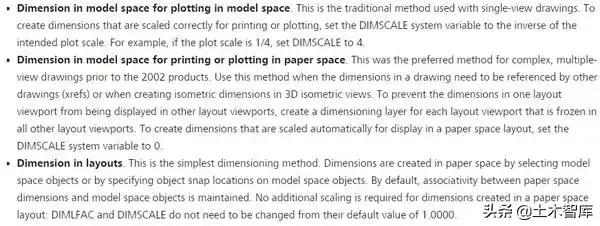
According to Zhu Xiaobao's tutorial,The most important point is to understand the relationship between the three worlds of "real world", "CAD virtual model space" and "printed paper drawings". . Once you figure this out, everything will be solved.
The "real world" and "printed paper drawings" are both visible and tangible. You can use a ruler to measure buildings in the real world, and you can also use a ruler to measure The length of the line segment on the printed paper drawing. The "CAD virtual model space" only exists in the computer and is just a digital file without any physical meaning. The so-called various ratios are the standards for the conversion between these three worlds.
Since there are three worlds, in fact, according to the arrangement and combination, there are three ratios between them, which are
- The ratio between the "real world" and the "printed paper drawings", commonly known as "Padding ratio", that is 1 to 100, 1 to 50, 1 to 25 and so on in the drawing specification.
- The ratio between the "real world" and the "virtual model space of CAD", commonly known as the "drawing scale", is generally 1:1 for convenience.
- The ratio between "CAD virtual model space" and "printed paper drawings" is generally called "printing ratio", such as the same CAD file, I can print it down on a piece of A4 paper to see for myself, or I can enlarge it and print it on A1 paper as a poster. This ratio generally depends on the actual situation. (It can be simply understood as printing photos. The same negative can print small 2-inch photos or print huge posters).
After reading Zhu Xiaobao's tutorial, Xiao Wang is full of confidence and feels that he has no problem at all.
On this day, the director came to Xiao Wang and said, "Xiao Wang, you have been here for a few days, let's draw a doorman's reception room to practice."
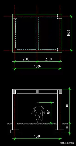
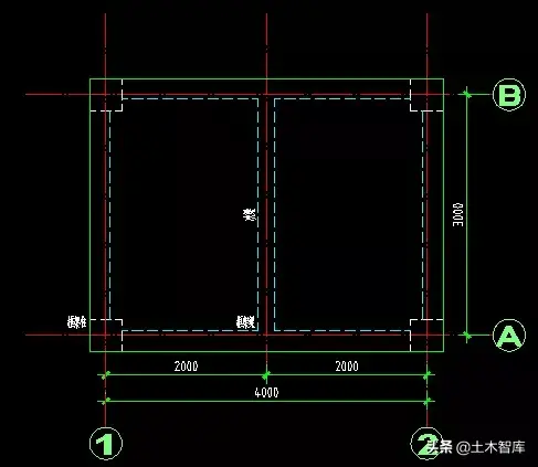
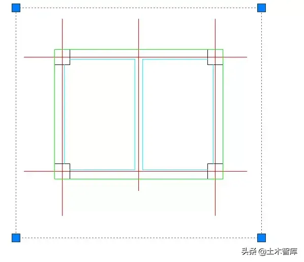
Xiao Wang thought excitedly, finally got something to do , It's time to learn and sell now, and show your talents. Open AutoCAD with confidence. According to Zhu Xiaobao's tutorial, the drawing is input in millimeters, the communication room is 4 meters wide in the "real world", which is 4000 mm, and 4000 is input in the "CAD virtual model space"; the length is 3 meters, and input in CAD 3000, the cross section of the column is 400 mm by 400 mm, which is a square of 400 by 400 in CAD... Draw all the graphics that need to be drawn according to this method, and the drawing at this time is like this:
Note that as of this step, only the relationship between the "real world" and "CAD virtual model space" needs to be considered, and there is no need to consider "printed paper drawings" at all. In theory, you can use any proportional relationship to connect the "real world" and "CAD's virtual model space". But the most convenient is undoubtedly 1:1, that is, 4000 mm in the "real world", and 4000 in the "CAD virtual model space". Direct input does not require any artificial conversion at all.
Drawing must be orderly and well-organized, so that it can respond to all changes without change, and can easily meet various changing requirements at any time. In order to do this, the first thing is to have the concept of layer management. Graphics must be strictly placed in the corresponding layer when drawing. For example, Xiao Wang adopted the structure drawing layer format recommended in Zhu Xiaobao's tutorial:

The graphics of the drawings are available, that is to say, we have reflected the "real world" into the "CAD virtual model space", and the next step is to reflect the "CAD virtual model space" into the "printed paper Drawings". In order to output the drawing, we must consider the beauty of the drawing, the legibility of the drawing, etc. For example, we need to add axis numbers, dimensioning, explanatory text, detailed drawings, etc.
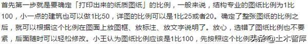
The first step is to determine the ratio of the "printed paper drawings" to the "real world". Generally speaking, the ratio of drawings for structural professionals is 1:100, and smaller buildings can also be made 1:50 , the scale of the detail drawing can be 1:25 or 20. After determining the scale of the entire drawing, you can place frames, labels, and text descriptions on the drawing according to this scale. Don't worry, it doesn't matter if you choose the wrong drawing scale, you can easily modify it later. Xiao Wang thinks that the scale of the drawing should be 1:100, so first draw according to this scale.
The scale of the drawing is 1:100, which means that the drawing is marked with 4000 mm, and the actual printed drawing is 40 mm with a ruler. In other words, a line segment of 40 mm on the drawing represents a length of 4000 in the real world. The CAD and the real world are 1:1, so the length in CAD is actually 4000. In other words, all the lengths in CAD are the actual measured length of the paper drawing multiplied by 100. Therefore, a font with a height of 2.5 mm on the drawing is actually 250 in height in CAD.
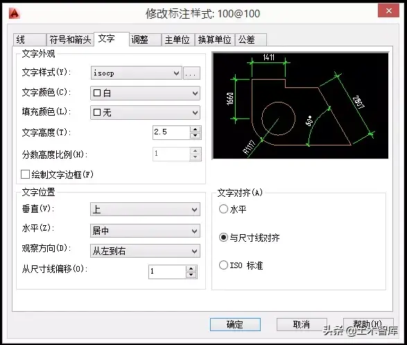
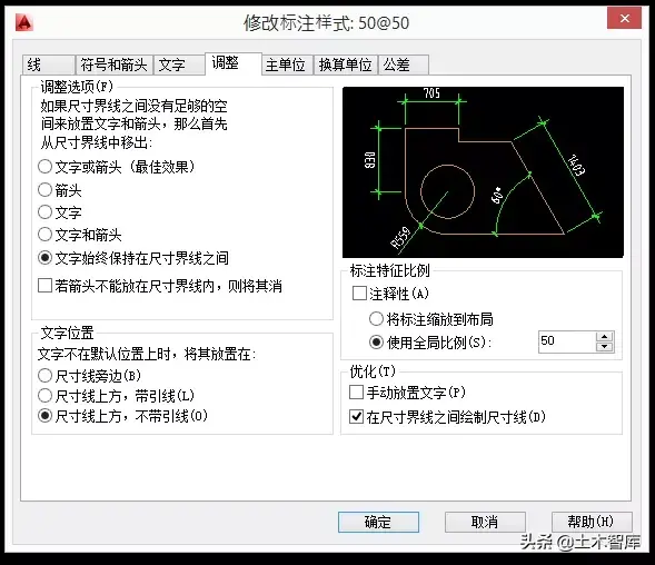
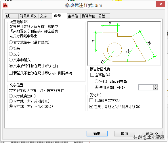
The second step is to consider dimensioning. First, set the appropriate dimensioning style according to the requirements of the drafting specification, such as font size, length of dimension line, size of arrow, etc.
Set the height of the text to 2.5 (corresponding to 2.5 mm in the actual paper drawing), and set the offset from the dimension line to 1 (corresponding to 1 mm in the actual paper drawing).
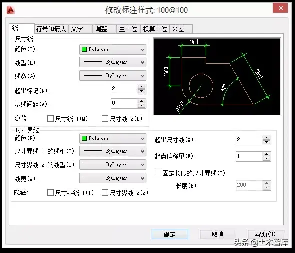
Set the exceeding mark to 2 (corresponding to 2 mm in the actual paper drawing), the exceeding dimension line 2 (corresponding to 2 mm in the actual paper drawing), and the starting point offset to 1 (corresponding to 1 mm in the actual paper drawing).
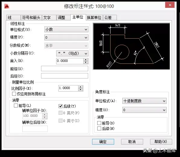
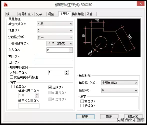
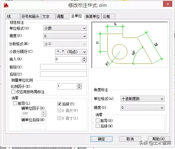
The measurement unit scale is set to 1, because the relationship between "real world" and "CAD's virtual model space" is 1:1, and 1000 mm in reality corresponds to 1000 in CAD.
The most critical step is to set the global scale of the label feature scale to 100. That is to say, multiply all the font sizes, arrow sizes, and dimension line lengths defined above by 100. In this way, the font height is defined as 2.5 in the dimension style, multiplied by the dimension feature ratio of 100, and the font height becomes 250 in the "CAD virtual model space".

So far, Xiao Wang has set the label style named "100@100", and then uses this label style to label the drawn graphics.
Next is the explanatory text. According to the drawing specification, the size of the explanatory text is about 3 mm, and the title text can be about 7 mm. In other words, the actual size of the explanatory text in CAD is 300 and 700, so after converting the ratio of 1:100, the height of the text is exactly 3mm and 7mm.
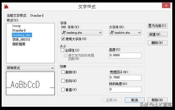
Set the text style, font, tilt, width ratio, etc.:
Then enter the explanatory text, and set the height of the text to 300, which corresponds to 3 mm in the paper drawing.
As a verification, if you put a dimension next to the text and check the height of the text, the size should be 300.
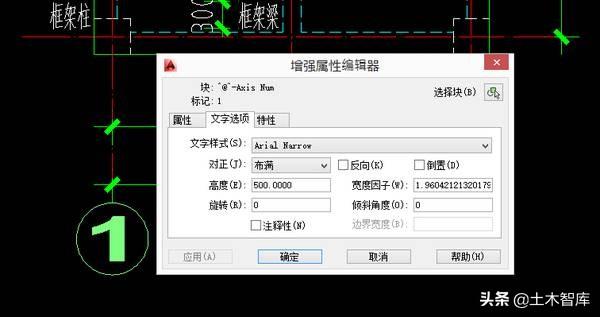
Then it is time to put the axis number. There are many ways, for example, the axis circle can be made into an attribute block. The text size of the attribute block is set to 500, corresponding to 5 mm on the paper drawing; the diameter of the circle is 800, corresponding to 8 mm on the paper drawing; the justification can be set to full, so that the number axis number will automatically adjust the width. Set the numerical label of the axis as a property of the block:
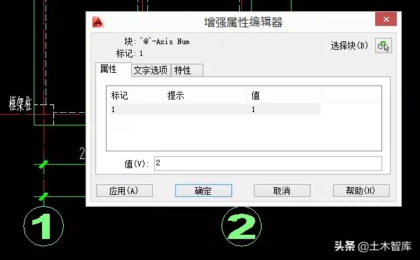
Then copy this attribute block to every place where the axis number is required, double-click, and enter the new axis number value:
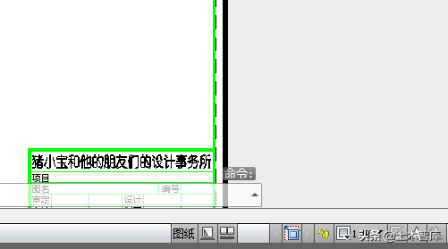
In the same way, the title of the drawing can also be made into a block with attributes, the drawing title and drawing scale are input by you, and the horizontal line below can be stretched to adapt to drawing titles of different lengths.
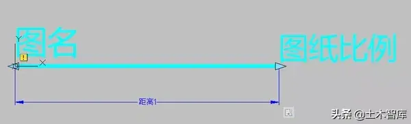
The effect of this title block is like this in the paper space. After entering the text of the drawing title, drag the horizontal line at the bottom with the mouse, and drag the right end point of the horizontal line and the scale number to the far right of the text:

If the text length of the title has changed, you can stretch the horizontal line at the bottom at any time:

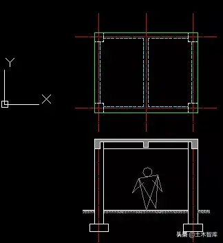
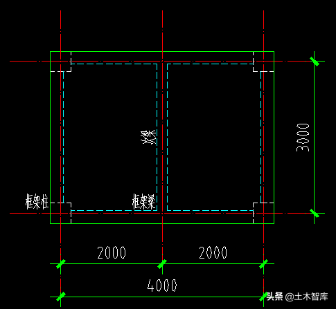
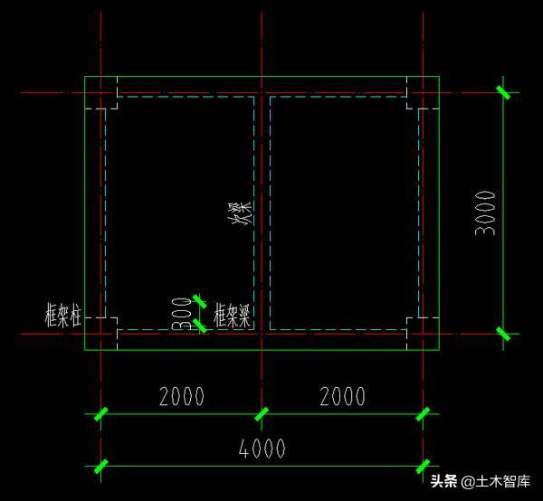
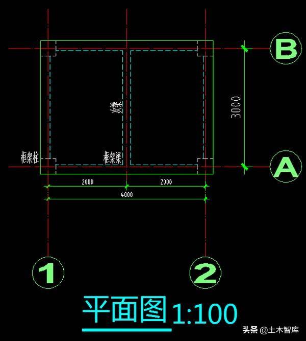
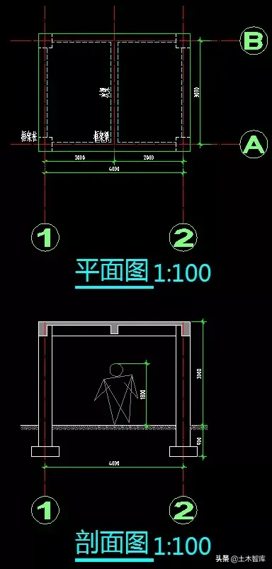
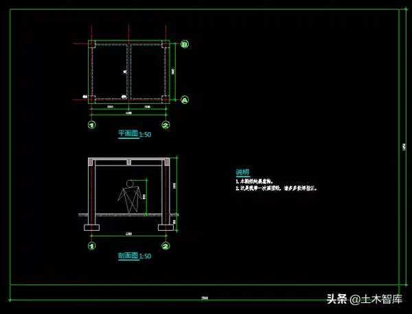
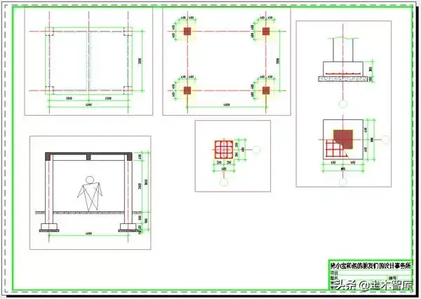
After setting the label, text, axis number, and title, Xiao Wang's drawing becomes like this:
At this point, the content of the drawing is basically completed, and the next step is to turn the "CAD virtual model space" into a "printed paper drawing". In order to print the drawings, the first step is to determine the size of the paper to be printed on, whether it is A4 or A1, horizontally or vertically?
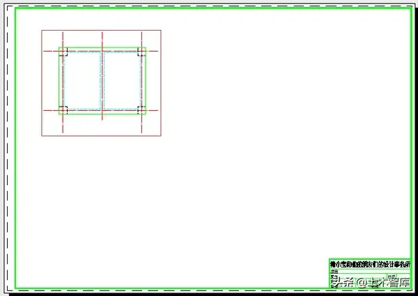
We already know that 300 in CAD is equivalent to 3 mm in paper drawings, so conversely, 3 mm in paper drawings is equivalent to 300 in CAD. The size of an A4 paper is 297 mm times 210 mm, so it is equivalent to 29700 times 21000 in CAD. Xiao Wang drew a rectangle of 29700 by 21000 in CAD as the frame of A4 paper:
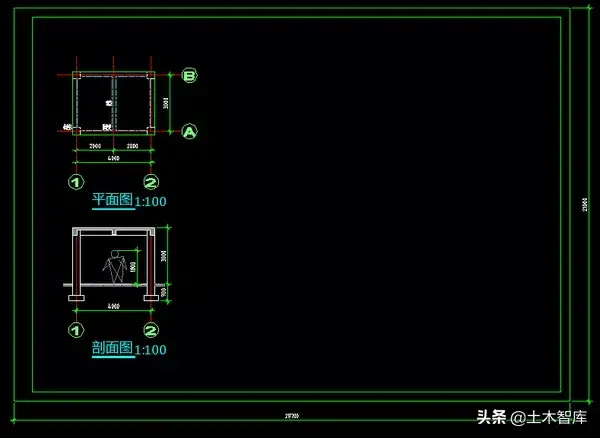
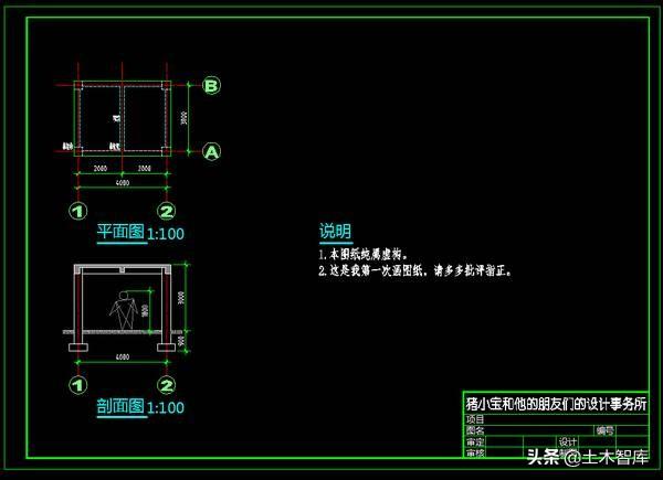
Add the label of the drawing and the explanatory text of the drawing, and you're done:
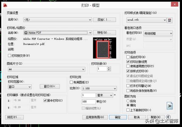
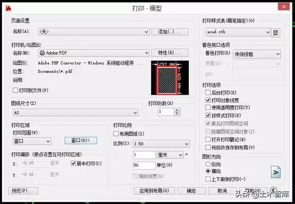
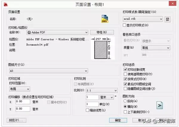
The next step is to print this drawing. The size of the drawing is A4 paper, so choose A4 paper in the printer; the actual size of A4 paper is 297 times 210 mm, and the size in CAD is 29700 times 21000, so choose 1:100 as the printing ratio when printing. Print the range selection window, and then use the mouse to select the range of the frame:
The printed effect is like this:
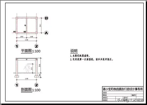
Print out this drawing, use a ruler to measure the distance between axis 1 and axis 2, it should be exactly 40 mm; measure the height of the explanatory text in the plan, it should be about 3 mm.
Xiao Wang took this printed drawing and ran to the director. After looking at it, the director said, "The young man works very quickly, and the drawings are not bad. However, this is a small communication room, and you use A4 drawings, which seem inconvenient on the construction site. Other drawings of this project do not match. How about you change it to an A3 drawing, and change the drawing ratio from 1:100 to 1:50. Okay?"
Xiao Wang returned to his desk and began to modify the drawing . Change the drawing scale from 1:100 to 1:50, what needs to be modified? Need to modify graphics? No, because the graphics are only the mapping of the "real world" and "CAD virtual model space", and have nothing to do with the scale of the drawing. No matter what the scale of the drawing is, the "real world" and "CAD virtual model space" are all 1 to 1 relationship.
The only things that need to be modified at this time are dimensions, text, titles, and axis numbers. Therefore, Xiao Wang returns to the above step:
According to the director's opinion, Xiao Wang revised the scale of the drawing to 1:50. The first thing to modify is the dimensioning. The original dimensioning style is 100@100. Now create a new dimensioning style called 50@50, and the rest remain unchanged. Just change the dimensioning feature scale from the original 100 to 50.
Note that the unit of measure scale does not need to be modified. Because this scale factor is only related to the ratio between the "real world" and "CAD's virtual model space", it has nothing to do with the scale of paper drawings.
After defining the new 50@50 label style, change the original 100@100 label style to this new 50@50 label style, and adjust the position of the label. Compare the difference between the dimensioning of the horizontal axis and the dimensioning of the longitudinal axis. The one that looks smaller has been changed to 50@50, and the one that looks larger has not been modified, and it is still 100@100.
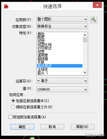
If the drawing is very large and complex, you don’t need to use the mouse to point one by one, you only need to use the quick selection, the selection condition is "All dimension styles equal to 100@100 dimensions", after selecting them all, set their attributes at once Just change it to 50@50.
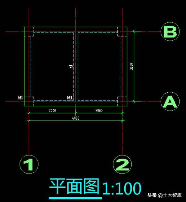
In this way, all the dimensions are modified to the new 50@50 style at one time, and then the position of the dimension is adjusted, and the dimension is adjusted:
Then modify the explanatory text in the drawing, the original text is 300 high, corresponding to 300 divided by 100 equals 3mm; now the scale of the drawing has become 50, so the text height should be set to 150 in CAD, corresponding to 150 divided by 50 equals 3 millimeters. Also use quick selection to uniformly modify all 300-high text in the drawing to 150:
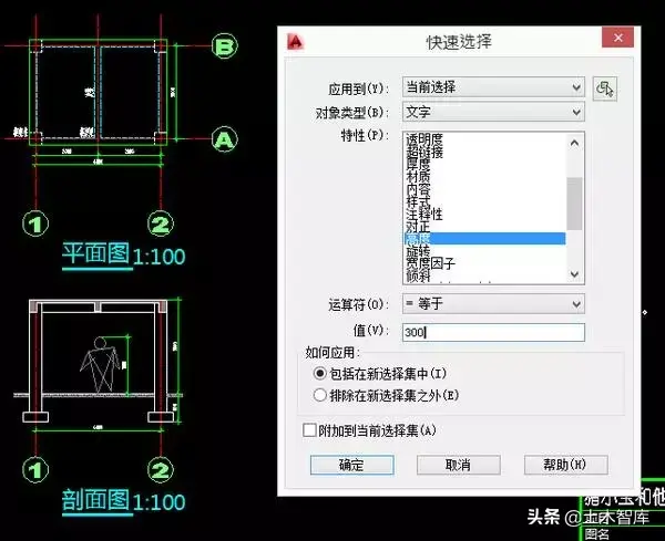
After selecting, modify the height attribute to 150, and the effect after modification is as follows:
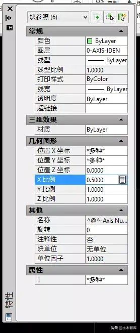
The next step is to modify the axis number and title. For the same reason, Xiao Wang needs to reduce these to half of the original. Since these are blocks with attributes, these blocks can be selected quickly. If the graphics are complex, there may be other blocks. At this time, you can use the name attribute as the selection criterion, and then modify the ratio of these blocks to 0.5 at once:
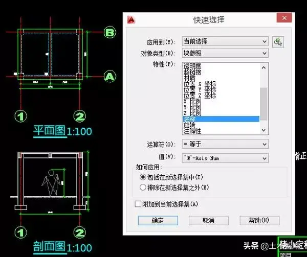
Here change all X, Y, Z scales to 0.5.
After setting the scale to 0.5, adjust the position of the axis number for the beauty of the drawing. At this time, the drawing looks like this:
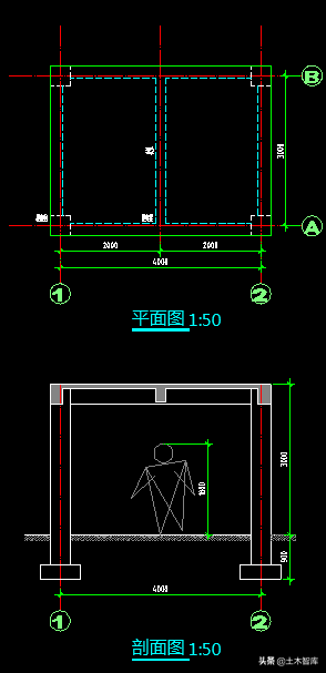
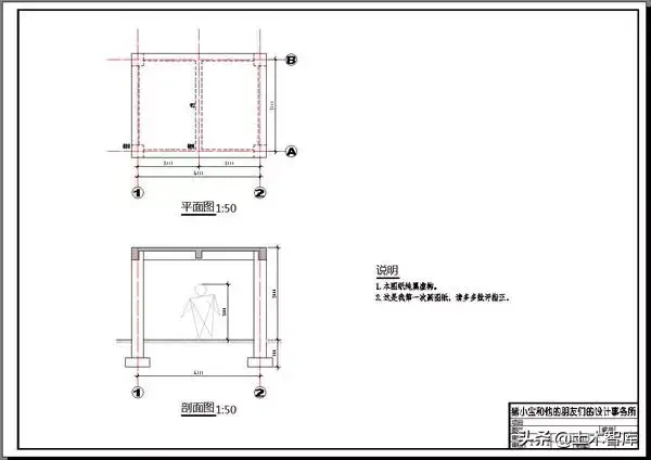
For the same reason, reduce the title block to 1/2 of the original size, and don't forget to change the scale of the drawing in the title to 1:50. Adjust the position of the drawing again, and the final part of the drawing is as follows:
Here is the problem with the frame. Now Xiao Wang needs to use A3 drawings. The size of an A3 paper in reality is 420 times 297 mm. Now 150 in CAD is equivalent to 3 mm in paper drawings, so conversely, 3 mm on paper drawings is equivalent to 150 in CAD. So the size of an A3 paper is equivalent to 21000 times 14850 in CAD (420 times 50 equals 21000, 297 times 50 equals 14850). Xiao Wang drew a rectangle of 21000 by 14850 in CAD as the frame of A3 paper:
The next step is to put the picture label in. Note that the overall size must also be reduced to 1/2 of the original size:

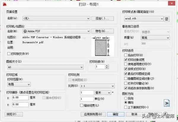
At this point, the modification of the entire drawing is completed. In the printer, set the paper size to A3 and the print ratio to 1:50:
The drawing prints out like this:
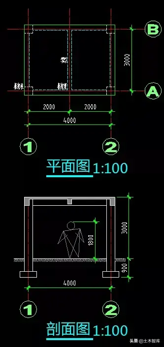
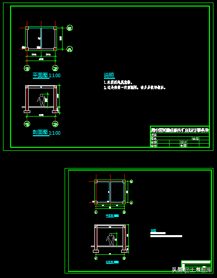
Let's put the above two paper drawings together for a comparison:
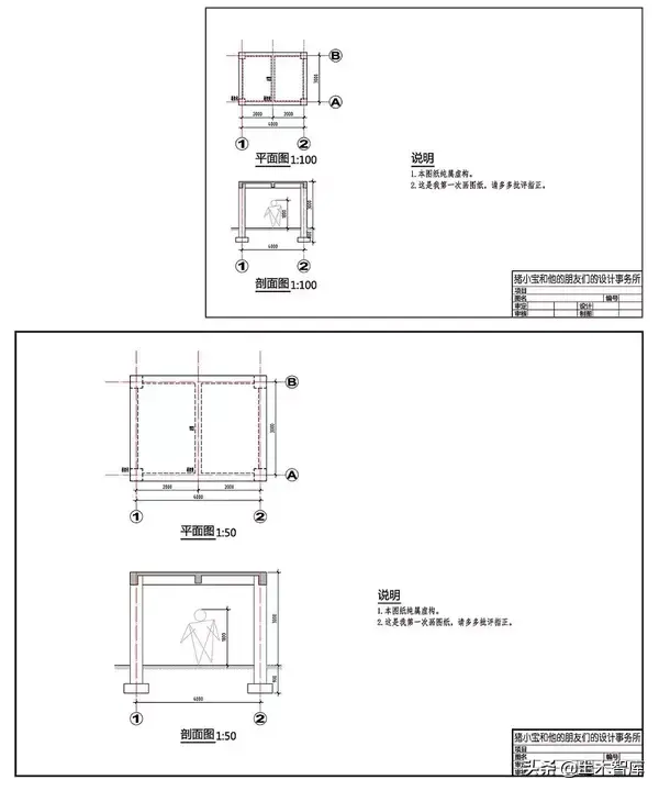
In the "printed paper drawings" world, the upper one is an A4 drawing with a scale of 1:100; the lower one is an A3 drawing with a scale of 1:50. If you measure it with a ruler, all the text heights, dimensions, titles, and labels are all the same. The only difference is that the size of the small house is doubled. The actual measured distance between the No. 1 and No. 2 axes in the above drawing is 40 mm, while the distance measured in the lower drawing is 80 mm. Comparing the two pictures, is the A3 below clearer and more eye-catching? It seems that the director still has a reason.
But in "CAD Virtual Model Space", the comparison between these two drawings is like this. The upper one is the 1:100 drawing of A4, and the lower one is the 1:50 drawing of A3. The only thing the two drawings have in common is that the small houses are the same size. The height of the remaining text, the size of the dimension, the size of the title, and the size of the label are all reduced by twice.
Comparing the "CAD virtual model space" and "printed paper drawings", Xiao Wang printed the above one as it is (1:100), and then got an A4 drawing with a drawing ratio of 1:100; The next one is enlarged twice and printed (1:50), and the A3 drawing with a drawing ratio of 1:50 is obtained. In this way, on the two "printed paper drawings", the text, labels, titles, and labels are the same size, but the small house is twice as large.

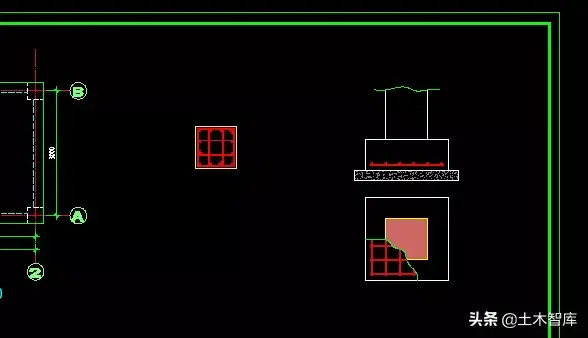
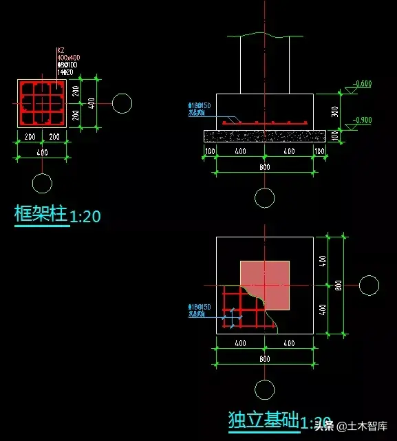
Xiao Wang took this new A3 drawing and went to the director again. The director took a look and said, "Hey, it's done so quickly, it's not bad. Well, we have a plan section, let's add a detailed drawing of the columns and the foundation." , usually use 1:20, and put it on the same drawing. How about it?"
Xiao Wang went back and continued to draw. First of all, the pillars and foundation details must be drawn, that is, the relationship between the "real world" and the "CAD virtual model space" must be established.
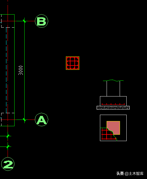
The drawing scale of these detailed drawings is 1:20, while the drawing scale of the plan view and section view is 1:50, which means that these two detailed drawings need to be based on the plan section drawing without changing other settings. Zoom in 2.5 times (50 divided by 20 equals 2.5).
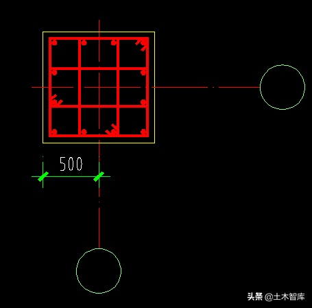
Don't worry about zooming. If you zoom directly, what should you do if you need to modify it in the future? For example, the column should be changed to 500, or the foundation should be changed to 950, and the foundation thickness should be changed to 250. At this time, Xiao Wang needs to make these detailed drawings into blocks first, and then scale this block.
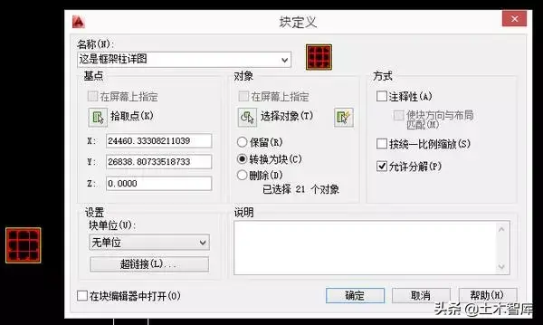
For example, define the detail of the frame column as a block named "This is the detail of the frame column", because the zoom operation is needed later, the block unit is best set to no unit.
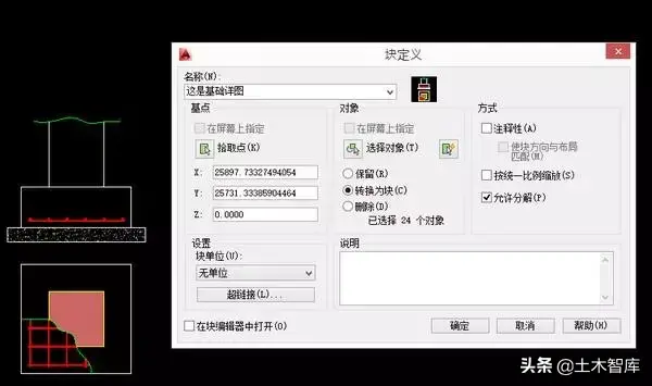
Likewise, define the details of the base as blocks.
Scale up the two detail blocks by a factor of 2.5 and adjust them to fit:
If you need to modify the content of these two detailed drawings later, you only need to double-click this block, and then modify it in the block editor. Added axes:
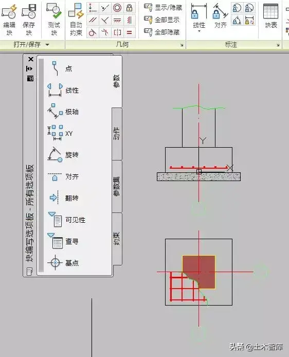
Or you can use in-place editing of the block, first draw the axis and circle, and then add it to the block:
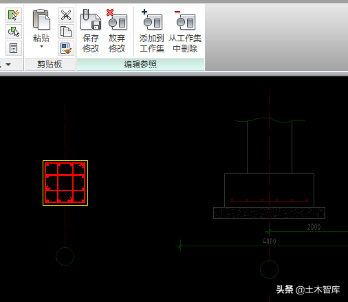
After saving the edits to these two blocks, the drawing now looks like this:
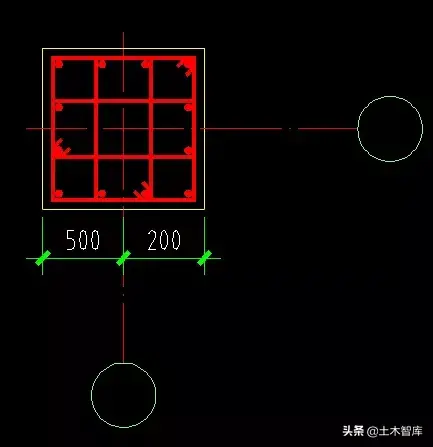
The next step is to add dimensions to these two details. Can you directly use the label style of 50@50? Probably not, because we have enlarged the detailed drawing by 2.5 times. If we still use 50@50 at this time, the result will be as follows. This is obviously not the detailed drawing size that Xiao Wang wants to express:
How should I do it? You can create a new dimension style called 20@50, which means that the 1:20 detail is used in the 1:50 plan. Compared with 50@50, only one place needs to be modified, which is to change the measurement unit ratio from 1 to 0.4 (20 divided by 50 equals 0.4). The rest of the settings are exactly the same.
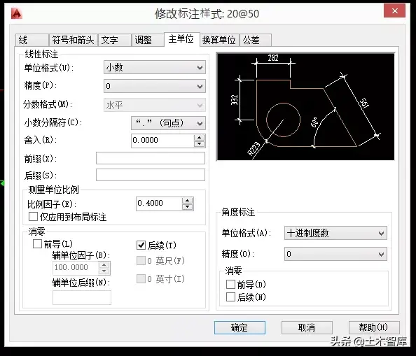
Put another dimension of 20@50, do you see the effect? The appearance of these two labels is exactly the same, the font size and arrow size are the same. The only difference is that the one on the left is 50@50 and the size number is wrong; the one on the right is 20@50 and the size number is correct:
Use the 20@50 dimension style to add dimensions to the two details:
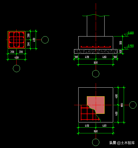
After dimensioning, the next step is to add captions and titles. Similarly, Xiao Wang needs to use the same 150-high text as the floor plan, so that after printing, it is equivalent to 3 mm on the paper drawing.
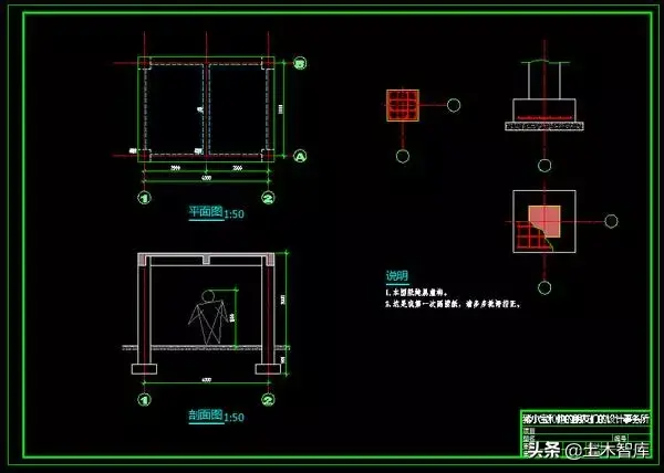
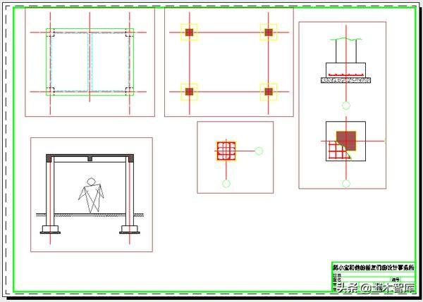
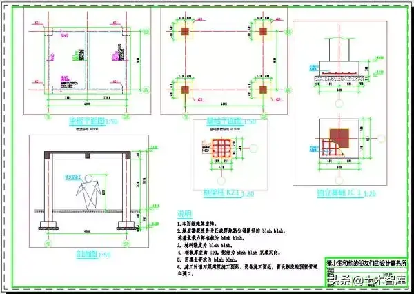
Finally, complete the design information and the foundation positioning plan, and a complete structural construction drawing is completed.
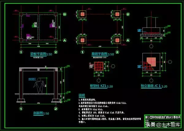
Drawings are printed on A3 paper like this:
Xiao Wang showed the modified drawing to the director, and the director looked at it and said, "There is no big problem, okay, let's show it to the chief engineer."
So Xiao Wang went to the chief engineer. After reading it, the chief engineer said, "How about it, you can still get used to drawing pictures."
Xiao Wang said, "Well, it's pretty good".
The chief engineer asked, "Is this drawing directly drawn and printed in the model space?"
Xiao Wang said, "Yes".
The chief engineer said, "There is also a layout system in CAD, are you familiar with it? It is to arrange each drawing into a layout space. Can you go back and compare the two methods? Then we can discuss it The advantages and disadvantages of these two methods."
Xiao Wang went back to his computer, opened Zhu Xiaobao's tutorial, and continued to learn the usage and meaning of layout.
The so-called layout is actually a virtual "what you see is what you get" "printed paper drawings", that is to say, the distinction between the three worlds is further clarified. The model tab corresponds to the "CAD virtual model space", while the layout tab corresponds to the "printed paper drawings".
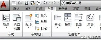
When Xiao Wang opens the layout tab, he must first set up the layout page:
In the page settings of the layout, set the paper size to A3 and the ratio to 1:1:
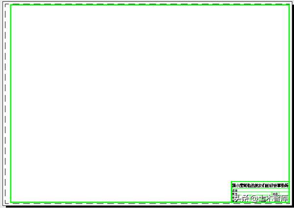
Then draw a drawing frame and label in this set A3 layout. Because we set the ratio of 1 mm to 1 unit in the previous step, Xiao Wang needs to draw a rectangle with a size of 420 times 297 in this layout as the A3 frame without any scaling. (You can also copy the A3 frame in the model, then reduce it by 50 times, and place it in a suitable position.)
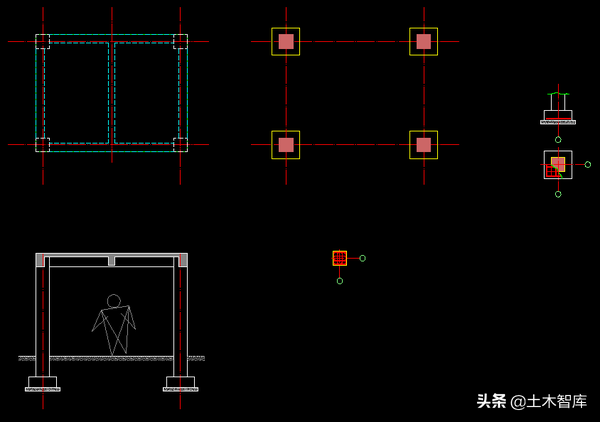
The next step is to prepare all the graphics in the model tab, that is, the graphics without any text descriptions and dimensions. Simply put, it is the graphics part that has just been completed from the "real world" to the "CAD virtual model space". These are the following graphics:
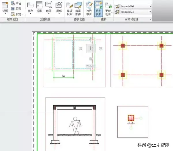
Go back to the Layout tab and create a new rectangular layout viewport:

After the viewport is created, it looks like this:
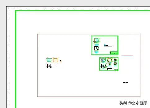
Select the bounds of this viewport around the first floor plan:
Then set the viewport scale in the lower right corner to 1:50:
At this time, the effect of the whole drawing is like this:
In the same way, add the viewports of the basic plan and section drawing, and set the scale to 1:50; add the viewports of the column detail and foundation detail, and set the scale to 1:20:
Then dimensioning, save the 50@50 dimensioning style as a new dimensioning style, name it dim, and change the dimensioning feature scale to 1:
Note that since we've set the 1:50 and 1:20 scales for the different viewports, the unit of measure scale is still 1:
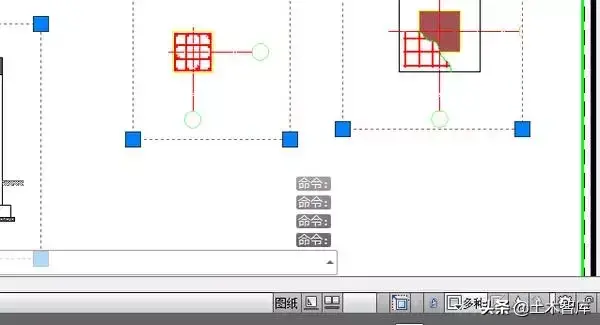
Before adding dimensions, in order to prevent misuse, you can lock all viewports first. If a viewport needs to be modified, you can temporarily unlock it first, and then lock it after the modification is completed:
After the viewport is locked, the button on the left of the "multiple" scale display button in the lower right corner will be displayed as locked. If you want to unlock a viewport, you can click this button to unlock it:
Then add the dimension of dim in the layout, without any manual adjustment, and without distinguishing between 1:50 and 1:20, all the annotations will automatically display the correct annotation values according to the ratio of different viewports:
The next step is to add various text descriptions, titles, etc., the method is the same as in the model space, except that the height of the text is no longer 300 or 150, but 3; the diameter of the circle of the axis number is no longer 800 or 400, and It is 4... Simply put, there is no need for any conversion, the number of millimeters should be on the paper drawing, here is the number, what you see is what you get.
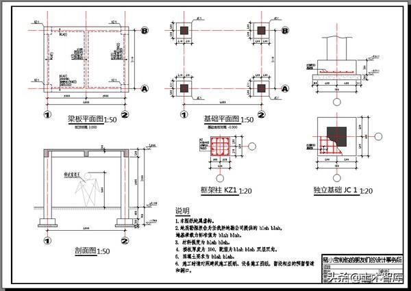
After the drawing is completed, print it into a real paper drawing. Before printing, remember to adjust the border lines of these views to non-printing layers, such as the default DEFPOINTS or other custom non-printing layers. Select A3 for the size of the printed drawing, the printing range is changed from the original window to the layout, and the printing ratio is 1:1:
The printed drawing looks like this:
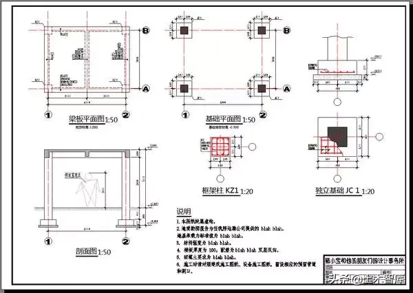
Different routes lead to the same goal, two different methods output the same paper drawings.
After learning how to use the layout, Xiao Wang went to the chief engineer. The chief engineer said, "How about it, what do you think of these two methods?"
Xiao Wang said, "I think they are different ways to the same goal, and each has its own advantages and disadvantages."
The chief engineer said, "Not bad, not bad, Talk about it."
Xiao Wang said, "The first method, all the annotations and texts are all in the model space, and if there are multiple drawings, they are all arranged in this model space. Different drawing scales require Setting different label styles, text heights, etc., seems a little troublesome, and it is not easy to understand when you are just getting in touch. The settings of various scale factors need to be carefully studied to understand."
The chief engineer said, "Then you What do you think of the second method?"
Xiao Wang said, "I don't know about this, I have to ask you for advice."
Xiao Wang said, "Yes. By the way, I heard that CAD can also set annotative dimensions or text. How is this used?"
The chief engineer said, "Annotative is the most recent version of AutoCAD The purpose of the newly released function is actually very simple. It is to reduce our workload and automatically match the label style and text size in the layout, so that we do not need to manually set and adjust. But at present, with the second This method is similar, but it’s still not very useful for us, and it’s a bit of a sledgehammer. Moreover, our drawings actually contain a lot of text information, which is used to indicate the size of components, reinforcement, special structural requirements, etc. If all annotations are used, the format after automatic text conversion is also a problem, and the file may be too large and redundant, which is inconvenient to use."
Xiao Wang said, "Then I heard that there are explorers or What do you think of the chief engineer of Tianzheng software?"
The chief engineer said, "I think these are tools, the same tool, some people use it well, while others don't. A chef can use a kitchen knife to carve flowers, but I use a kitchen knife Maybe you have to cut your own hands, so the key is to understand the principles of these tools, use them selectively, use their good parts, and don't be bound or restricted by their bad parts."
Xiao Wang said , "Are they like point-and-shoot cameras, which can provide relatively old-fashioned things, but can't produce really good things?"
The chief engineer said, "It kind of means that. After all, you have to know how to take pictures. The reason is to use a good camera to take good pictures. The same is true for our drawing. You can’t just rely on those foolish software. You have to understand the reason yourself to draw really good drawings. In fact, the software of Explorer is to integrate these functions. In the black box, you can use it, but there is little room for you to customize. It is indeed a bit of a point-and-shoot camera. If you practice CAD drawing in this way, it is actually equivalent to learning the principle of photography. In the future, manual, automatic, and foolish You can use it, and you can even modify or even make your own camera."
Xiao Wang said, "Then why do you think this drawing is so important?"
The chief engineer said, "Actually, in our industry Many people are prejudiced and think that the most important thing is calculation and analysis. Drawings are just drawing. In fact, drawing is very important. It is the language of our engineers. No matter how good your design is, the drawing is a mess, and even serious low-level mistakes occur. , Isn’t that a waste of all previous efforts. Not every engineer has to draw their own drawings, but at least every engineer must have the ability to draw their own drawings.”
Xiao Wang said, “I heard that BIM will soon be big The scale has been promoted, so do we still need these?"
The chief engineer said, "BIM is of course a good thing, but I think the reasons are the same. If a person can't use CAD well, it's hard for me to imagine that he can use it well. BIM.These engineering drawing and modeling software are not mechanical operations. You have to consider how to organize the entire project, how to deal with changes conveniently and quickly, how to complete the project quickly and well, how to cooperate with a team, and a graphic file Temporary substitutions can be seamlessly connected. These are all knowledge, I think this BIM and the current CAD are interlinked. "
Xiao Wang said, "Yes, yes, sometimes the rhythm of our industry is very urgent, and improving efficiency is very important."
The chief engineer said, "When I first started working, I remembered that a colleague The dimension style will not be set, and the dimensions are copied from different drawing files, some are large and some are small, and the proportions of dimension features and measurement units are also different. Opening such a graphic file, the light layer has to be There are a hundred of them, with all kinds of names, no matter how pu they are, they can’t be finished. Some people even use the format brush to click one by one with the mouse. There are so many drawings in a big project, just click the mouse It can be clicked for an hour. It is inevitable that some points have been missed. Some places have not been changed. In fact, when you set the label style and layer when drawing, you need to modify it. One quick selection, one attribute modification, 2 seconds Some people think it is troublesome to set up these styles, but in fact, sharpening a knife is not the same as chopping firewood. Really, using snacks when drawing, can save countless time when modifying later."
Xiao Wang said, "Yes , I practiced this time, and I think it is very important. Small projects are like this, let alone big projects."
The chief engineer said, "Oh, I forgot the time to chat with you, I have to go , to pick up my wife from work."
Xiao Wang said, "Go slowly, I have to pick up my girlfriend too!"
Note: Everyone is welcome to pay attention to the editor's WeChat public account "Civil Engineering Think Tank", which contains a lot of information on the construction industry compiled by the editor, including the first construction, second construction, cost, fire protection videos and courseware, everyone is welcome to join strong>
Articles are uploaded by users and are for non-commercial browsing only. Posted by: Lomu, please indicate the source: https://www.daogebangong.com/en/articles/detail/This%20article%20has%20solved%20my%20CAD%20drawing%20ratio%20problem%20for%20many%20years.html
 支付宝扫一扫
评论列表(196条)
测试