
Good lesson recommendation:
SU Tutorial: click me solidworks tutorial: click me < /span>rhino tutorial: click me
CAD dynamic block: click me CAD electrical: click me cad garden: click me
SW Motion Simulation: click me Tianzheng Construction: click me cabinet design: click me
Weak current cad: click me CAD tooling: click me cad layout : click me
More video tutorials: click me to view
Nowadays in the design industry, CAD software has been used in all walks of life. How to make a template that suits you or meets corporate standards is the basic skill of a CAD user. File template settings mainly include: unit settings, text style settings, dimension style settings, leader line style settings, table style settings, layer settings, point styles, title bars and other information columns, etc. input. In the early days, some national standards stipulated CAD drawing specifications, mainly including:
| GB/T 10609.1-2008 Technical Drawing Title Bar |
| GB/T 14689-2008 Technical Drawing Drawing Size and Format |
| GB/T 14691-1993 Technical Drawing Font |
| GB/T 17450-1998 Technical Drawing Drawing Line |
| GB/T 14665-93 Drawing Rules for Computer Information Exchange for Mechanical Drawing |
Set the text style according to your own needs. Generally, different industries, different fields, different marking methods, or to improve the readability of large files, for example, some large projects often require division of labor Collaborate, and finally integrate the patterns, dozens or even hundreds of font styles... The author suggests that the number of text styles should not be too many.
[Shortcut key]: ST (full spelling is style)
Menu bar: [Comment] - [Text]

Figure 1.1
As shown in Figure 1.1, click the small arrow in the lower right corner of the tab to open the "Text Style" setting dialog box, as shown in Figure 1.2. Text style setting is relatively simple, and possible risks include: The required font is not inCAD Font library; if you send your own file to others, the personalized font will be lost . (Refer to the previous tweets of the official account of CAD Self-study Network)
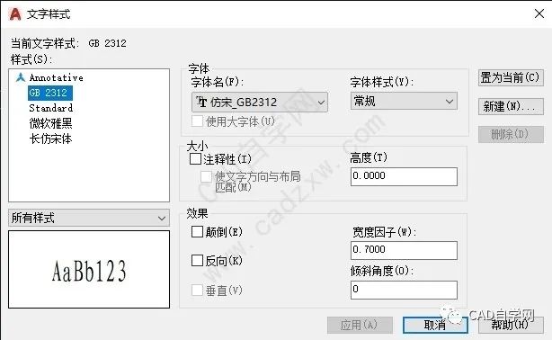
Figure 1.2
2. Dimension style setting
Set the label style according to your own needs. The standard styles of different industries are often different. Let's take the mechanical profession as an example to set.
[Shortcut key]: DIMSTYLE
Menu bar: [Comment] - [Annotation]
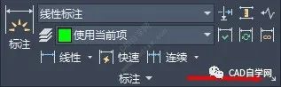
Figure 2.1
As shown in Figure 2.1, click the small arrow in the lower right corner of the tab to open the "Dimension Style Manager" dialog box, and the "Standard Style" setting dialog box is shown in Figure 2.2. Generally, there can be multiple annotation styles, and the default style of the software is "ISO-25 style". The usual method is to create a new style based on this style, as shown in Figure 2.2. "Angle" and "Linear dimension" are created later.
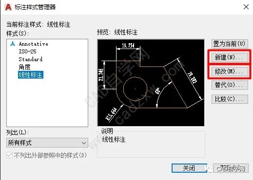
Figure 2.2
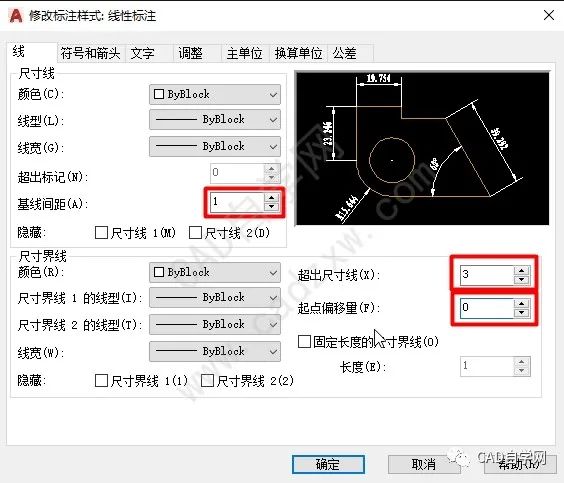
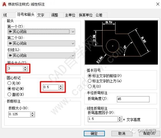
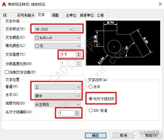
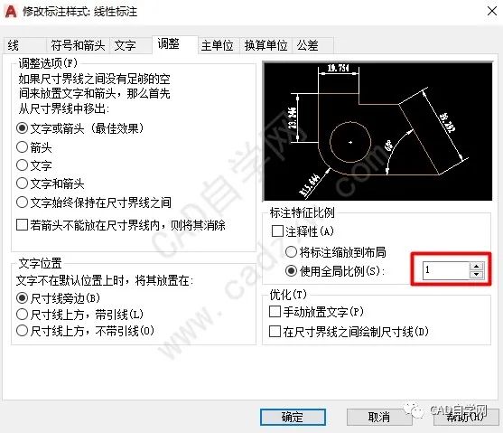
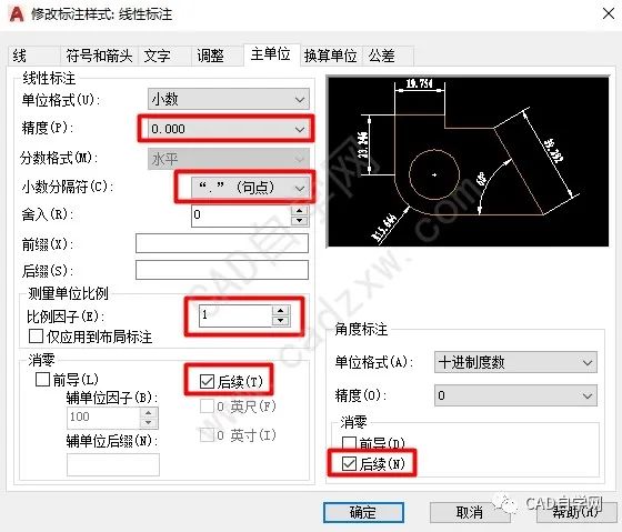
After creating a new style, click "Modify" (generally, this step is required), and the following "Modify Dimension Style Dialog Box" will pop up. This dialog box contains 7 tab pages (generally, " Conversion Unit" and "Tolerance" can not be adjusted for the time being), the modification required for each tab page is shown in the figure below.
3. Leader style setting
The setting of the leader line style is relatively simple, and can be set according to one's own needs.
[Shortcut key]: MLEADERSTYLE
Menu bar: [Comment] - [Leader]
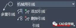
Figure 3.1
As shown in Figure 3.1, click the small arrow in the lower right corner of the tab to open the "Multiple Leader Style Manager" dialog box, as shown in Figure 3.2. Similarly, create a new style based on the original style "Standard". After creating a new style, it is generally necessary to modify it, as shown in Figure 3.3.
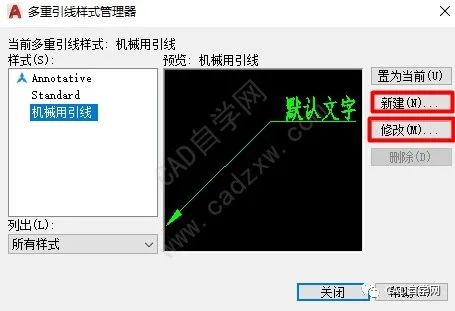
Figure 3.2
After clicking Modify, there are 3 tabs in the pop-up dialog box, which can be modified according to your needs.
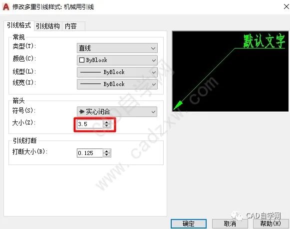
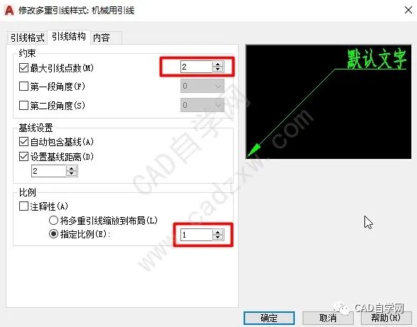
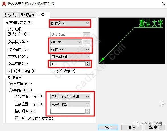
Figure 3.3 Modify Multileader Style Dialog
4. Layer Properties Manager Settings
Layers are also an important part of CAD, they make the drawing interface of CAD transparent. In fact, in the author's opinion, the purpose of setting layers is to improve the readability of the document content, and to facilitate modification. As shown in Figure 4.1, the "Layer Properties Manager" dialog box.
[Shortcut key]: LAYER
Menu bar: [Default] - [Layer Properties]
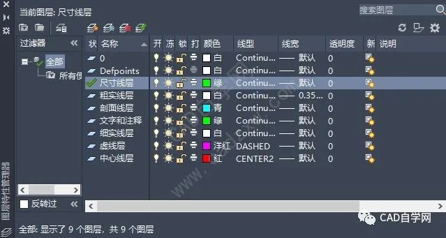
Figure 4.1
The author suggests that, in addition to the default layers of the system, the number of new layers should not be too many.
5. Title bar
The drawing method of the title bar is also relatively simple. Here we mainly mention the "attribute definition" function in CAD.
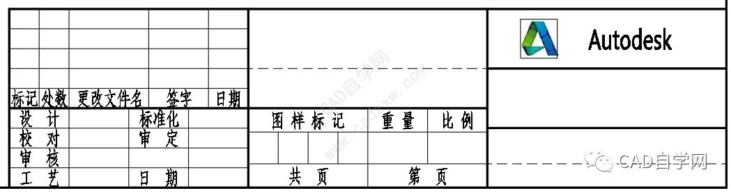
As shown in Figure 5.1, this is the title bar specification given in the national standard, where the line height of 7mm is suitable for font size 5, and the line height of 5mm is suitable for font size 3.5.

Figure 5.1
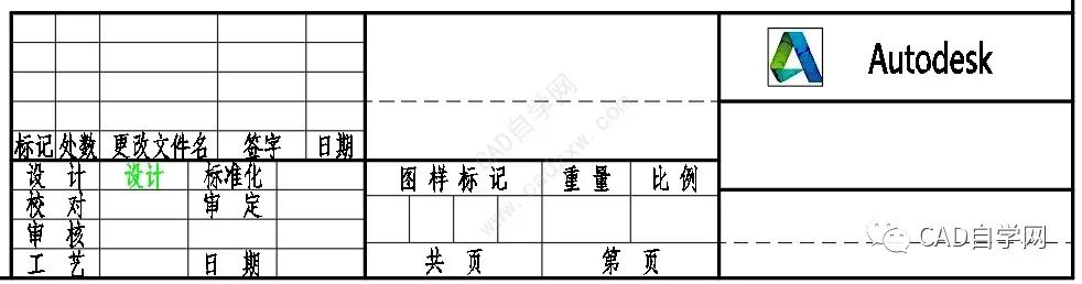
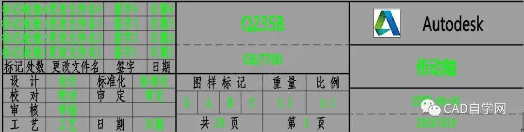
As shown in Figure 5.2, it is a custom title bar. Generally speaking, in an enterprise, the name of the unit is fixed, the rest of the green fonts are variables, and the black system is the marked content, which is generally fixed. Our goal is to make it easier to enter text in the title bar to achieve the effect shown in Figure 5.3. If you want to change the content in the title bar, you don’t need to use the multi-line text tool to modify one by one, but directly modify the corresponding value through the enhanced property editor.
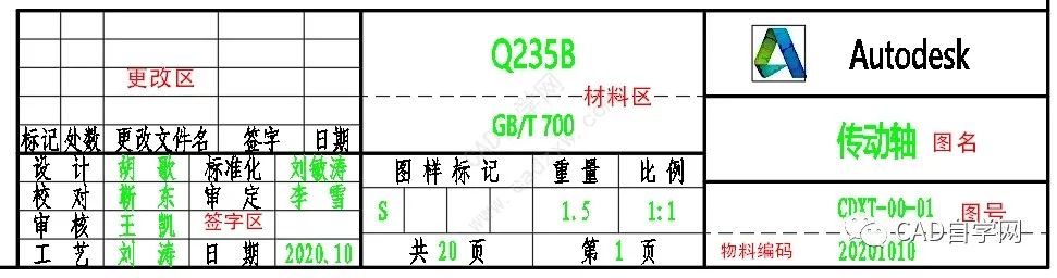
Figure 5.2
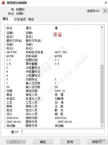
Figure 5.3 Enhanced Property Editor
The usage of the Enhanced Property Editor is described in detail below.
Step 1: Edit fixed content, as shown in the figure below, draw a table.
The specific size of the table is omitted, and the text uses the multi-line text tool. If the format is A3 or A4, size 3.5 is recommended; size 5 is recommended for A2 and above.
Step 2: Edit variable content.
[Shortcut key]: ATT
Menu bar: [Insert] - [Define Properties]
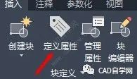
Click the "Define Properties" button to open the following dialog:
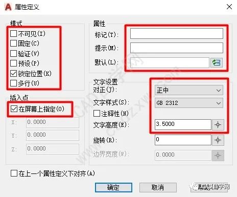
Fill in the first variable in "Mark", such as "Design", and fill in the prompt of the first variable in "Prompt", such as "Designer". If the designer is fixed, you can enter it in " Default" to fill in the default name.
Fill in all possible variables in the title bar in the form of "attribute definition", as shown in the figure below:
After filling in, make the border and text in the title bar area into blocks, shortcut key: B. After making a block, you can see that the green text is automatically hidden. At this point, double-click this block, and the "Enhanced Property Editor" dialog box will pop up, as shown in the figure below:

Each entry can be typed by modifying the "value". The final effect is shown in Figure 5.2. Finally, the title block can be saved as a permanent block, so that when making a template for the next format, it can be directly imported.
Finally, save the file as a drawing template format: .dwt format for next use.

At this point, the CAD template is finished.
CAD self-study network video number
END A design sharing site with attitude and materials CAD self-study network WeChat ID: cadzxw ClickRead the original textLearnMore tutorials< /section>


Articles are uploaded by users and are for non-commercial browsing only. Posted by: Lomu, please indicate the source: https://www.daogebangong.com/en/articles/detail/Teach%20you%20how%20to%20make%20CAD%20template%20files.html
 支付宝扫一扫
评论列表(196条)
测试