
1. General regulations
1, medium and small bridge spans should adopt standard spans as much as possible, mainly including 8m, 10m, 13m, 16m, and 20m, except8m adopts reinforced concrete structure, the rest adopts pre-tensioned prestressed hollow slab.
2. Bridge slabs and girders should be prefabricated in factories, and integral cast-in-place girders can be used due to the limited transportation conditions of the connecting roads, but the bridge span should not exceed 10m, and generally give priority to the use of reinforced concrete structures.
3The bridge spans across the river generally adopt single span or odd number of spans, and it is not allowed to lay foundations at the center of the river unless in special circumstances.
4. The layout of the bridge length should be based on the uncompressed river course as much as possible, and it should be long rather than short. But attention should be paid to the connection with the intersection road at the bridge head.
5, the bridge deflection angle should be consistent with the direction across the river, the maximum deflection angle is 45°, naturally It is not advisable to adopt plans such as cutting bends to straighten, partial rerouting and sequential connection of river courses. If it cannot be consistent with the direction of water flow, the span of the bridge should be increased as much as possible to reduce the number of piers in the water.

6, Separately reconstructed bridges should not be set on curves. The bridge on the curve should adopt the straight construction of the curved bridge, the bisected distance, the layout of the radial broken line, the reservation of the hat beamT wet joint, the adjustment curve of the guardrail, etc. The method is to adjust the curve. In extreme cases, the method of increasing the bridge width can be used. Generally, it is not suitable to use cast-in-place beams.
7The lower part of the bridge should generally adopt cast-in-situ pile foundation.
8. Concrete structure should be used for bridge deck pavement for separate reconstruction, and the minimum thickness should not be less than 12cm.
9, The building height of the bridge should be at least 50cm above the flood level according to the code requirements50cm Control, the longitudinal slope on the bridge should not be greater than 4%, and the approach road should not be greater than 5%; Urban mixed traffic section shall not exceed 3%.
10, weak current and water pipe facilities can cross the river through bridges, and it is strictly forbidden to use or pass through bridges for flammable, explosive, high-pressure and other pipeline facilities.

Second, major mistakes are not allowed
1, bridge position coordinates, detail structure size, elevation error;
2, major errors in engineering quantity (such as double-width is measured by single-width, and component quantity is doubled);
3, the size of the main components is inconsistent (such as the overall drawing and the structural drawing are inconsistent; pile distance, pile diameter, pile length, elevation and cover beam size, etc. inconsistent).

Third, the work that should be done in the early stage
1Basic information of on-site investigation: clear needs of the owner, flood level, navigation situation, old bridge situation, related planning of river and road, surrounding environment (with or without buildings) : nearby buildings, water conservancy facilities, bridge pipelines, etc.), whether the high-voltage pole lines and wiring roads are convenient for beam transportation, whether the conditions for hoisting plate beams on site meet the space requirements, if the old bridge is an expanded foundation or whether nearby high-voltage lines affect piling, etc.);
1Determination of bridge span:
aFor small and medium-sized bridges on rural roads, use them with caution when considering beam transportation conditions, hoisting conditions and high water levels20mslab girder.
bTry to use the standard span, because the subsidy standard of the provincial government agricultural bridge has changed, and the subsidy standard of small and medium bridges is the same, so it is not recommended 10+11+10 and so on are similar to "hard-built middle bridge".
cThe size of the bridge span should be reasonably arranged in combination with the width of the river and the construction of the existing bridges upstream and downstream. If necessary, it should be discussed with the local water conservancy department or management department
The door negotiates to determine the written agreement on bridge span, bridge width and so on.
dThe deflection angle of the bridge should be as consistent as possible with the river course, using 5º system. The flyover should be strictly controlled to be consistent with the direction of the route.
②Designed water level: For municipal rivers and waterways (including other grades), the design flood level and navigable water level must be clearly defined; And understand the upstream and downstream bridge spans, beam bottom elevations, etc. at the bridge location, in order to collect basic information for the longitudinal section data.
③Investigation on old bridges: the span and structural form of old bridges, if it is an old arch bridge with a large span, it is mostly an enlarged foundation. If pile foundations are used in the later design, it is required to After the foundation is excavated cleanly, the bored piles shall be constructed after filling and compacting. When calculating the length of the abutment piles, the negative friction resistance shall be taken into consideration and properly lengthened. Pay attention to the piers of the new bridge to avoid the piers of the old bridge.
2Investigate the road grade, width, road surface structure of the bridgehead connection, whether there is room for optimization of the bridge position, whether the bridgehead is located at the intersection, the elevation connection of the bridgehead connection, etc.
3Strengthen communication and reporting, and formulate a mature bridge plan that should be approved by the industry and relevant department heads.
4. Investigate the upstream and downstream bridges and road network conditions. If the detour distance is too long, after coordinating with the local government, you can consider setting up a pedestrian bridge, and at the same time, the engineering quantity should be calculated enter.

4. General requirements for drawings
1, font, character height strictly implement the requirements of the court documents:
Header4.0, Chinese text in the drawing2.5, description3.0 (imitation Song-GB2312, wide0.8)) span>
Numbers use fsdb, width0.75; for headers with subscripts , use4.0 above, and 2.5 below
2, line shape: table border, steel bar line, line width0.4;
The topographic map in the plan view uses 8#line, line width0.1 , faded if necessary; the rest of the line width is uniform0.2; the title spacing is 1, the top is thick and the bottom is thin; the dotted line and the center line in the figure should be clearly indicated by dotted lines.
3, ratio
The bridge deck elevation and pile number in the overall drawing are recommended in CAD to be arranged according to the actual situation. The main drawings should be drawn in proportion, and the schematic part should pay attention to the size relationship, and the proportions of various line shapes and truncated symbols should be moderate to ensure that the drawings are beautiful.
4. For bridges that are framed or have different components, the title of the picture in the picture frame should be marked in brackets. Such as: general structural diagram of bridge piers (motor vehicle lanes).
5. The quantity summary table in the drawing must be subscripted, indicating how many are convenient for self-examination and later review. For example: a summary table of the number of piles (a total of 2 abutments).
6, the expression of the same component must be consistent.
7 If the cross-sectional drawing is half drawn, the title should be marked. Such as: half plane, half elevation, 1/2plane, etc.
8. For bridges with oblique angles, the distance between piles shall be taken as an integer. >/cosangle etc.
9, obsolete and non-standard symbols must not appear. Such as: I grade steel, II grade steel, 40#Concrete etc.
10, if there are separate volumes on the drawing, it must be marked: “Second Volume Two Volumes" and "Part Four Bridges and Culverts", “Second volume two volumes”etc.

5. Matters needing attention before signature and publication of drawings
1. When signing the drawing, it should be ensured that the review has been signed and signed, and the relevant proofreading sheet should be attached.
2. Before the chief engineer in charge signs, the bridge type plan should be communicated and confirmed with the chief engineer in advance, and the main plan such as bridge span and bridge width should not be temporarily changed Case.
3, good progress control, no procrastination, avoid temporary publication, and leave enough time for the reviewers to look at the pictures.
4. Before the drawings are sorted out and published, the relevant processes must be improved, such as geological survey reports, ISO, etc., and Self-examination should be conducted from beginning to end, and there must be no missing pages or fewer signatures.
5. For later changes, you should communicate more with the person in charge and the chief engineer to coordinate the change plan. The reasons for the change must be stated in the change order, and non-voluntary changes must be signed or approved by the competent department.

6. Notes on detailed structure
⑴Design Description
1. In addition to old bridge reconstruction projects, outdated specifications should not be quoted, especially the following:
(1) "Anchors, Clamps and Connectors for Prestressed Tendons" (GB/T14370 -2015);
(2) "Steel Strand for Prestressed Concrete" (GB/T5224 -2014)
(3)"Technical Regulations for Concrete Structures with Welded Reinforced Mesh" (JGJ/T114 -2014)
4) Code for Seismic Design of Highway Engineering (JTG B02-2013)
(5) "Technical Specifications for Corrosion Protection of Concrete Structures in Highway Engineering" (JTG/TB07-01- 2006)
(6) "Code for Durability Design of Concrete Structures"(GB/T50476-2008)
(7)《Welded Steel Mesh for Reinforced Concrete》(GB/T1499.3-2010)
2, all numbers in the description should use "TIMESNEW ROMAN" characters.
3, used in geological datafa0, qik,Q3al+pl Pay attention to superscript and subscript issues.
4. For urban bridges with sidewalks, the crowd load shall be in accordance with the "Code for Design of Urban Bridges" (GJJ11-2011) Clause 10.0.5usesxxxkPa.
5The renovation of the old bridge should state the basic situation of the old bridge, the degree of damage, and the reason for the demolition, etc.
6. If the engineering quantity is included in the route, it must be explained in the description.
7, pay attention to the renovation project and add the following related content:
(1)Since this project is an old bridge renovation project, the difficulty of drilling piles at the foundation of the old bridge should be fully considered during construction. If necessary, measures to penetrate the foundation of the old bridge should be prepared;
(2) During foundation construction, if the geological conditions are found to be inconsistent with the drawings, supplementary drilling shall be carried out and confirmed by the supervisor engineer and the owner After that, contact the design unit in time;
(3) Before the construction of the bridge, the construction unit should prepare a safe and reliable bridge demolition plan, and report it to the owner unit in time for review After agreeing, the old bridge can be demolished;
(4) After the bridge renovation is completed, it should be well connected with the existing road;
(5)For navigable rivers, the foundation of the old bridge should be demolished to below the planned river bed line2m< /span>.
8, For bridges laid with asphalt concrete, please indicate“ Flexible waterproof adhesive layer”, add requirements in the description”Before spraying the flexible waterproof adhesive layer on the bridge deck, First remove oil, garbage, etc., then thoroughly clean the base surface, and then blow the base surface clean with a dust blower. The waterproof layer is sprayed 3 times in total (dosage 0.6~0.8kg/m2), the next layer should be sprayed after the previous paint is dry. The waterproof material must meet Relevant technical requirements stipulated in JT/T535-2004"Waterborne Asphalt-Based Waterproof Coatings for Roads and Bridges".”
For "Epoxy Bituminous Waterproofing"< span >, specify"Water-based epoxy asphalt waterproof bonding layer is used for bridge deck waterproofing, and the bridge deck waterproof levelIgrade, the design service life15years, the amount of materials and related requirements should meet the local standard of Jiangsu Province "Construction of Water-based Epoxy Waterproof Adhesive Layer on Cement Concrete Bridge Deck Technical Specification "(DB32/T2285-2012)Relevant regulations".
9. For the description of culverts, it is necessary to add "The elevation, position, intersection angle and length of culverts should be reviewed according to the actual situation on site. If there is a large deviation from the design, Please notify the design unit in time to make changes."
10For batch agricultural bridges, a list of protection layers for each component should be added.
11. For municipal bridges, a new article should be added, "Before construction, the location of the bridge and all underground pipelines nearby should be checked. The department requires that the relocation and protection be done in advance, otherwise the construction will not be allowed.”
12, the bridge description must include the bridge's seismic fortification level, service life (replaceable component years), structural durability requirements, steel structure anti-corrosion scheme, bridge operation period Maintenance precautions, etc.

II Project Quantity List
1The number of bridge and culvert projects shall be kept to one decimal place.
2The corresponding quantity statistics are clear, and there must be no missing or missing items.
2 If there is an old bridge to be demolished, the length, width, upper form and lower form of the old bridge should be stated in the remarks.
3. For the protected river course, the amount of protection work destroyed during construction and the amount of restoration work should be included.
4, other quantities should be included in the remarks: such as the number of street lamp sets, PVCpipes, etc.
III Bridge layout plan
1, what should be marked on the drawings: start and end point and center pile number, bridge width, intersection turning radius, north arrow, basic road composition, road name, River name, waterway grade, etc.
2, the map of the floor plan, the stake number and font on the road should pay attention to the proportion, and it is not allowed to copy it.
3. The overall proportion of the floor plan should be coordinated. It is necessary to be able to see the basic structure of the bridge and the location of the environment.
4. If there are high-voltage poles, cables, and civil facilities near the bridge, the construction distance should be ensured. should be reflected in the quantity table.
5, control points and control point result tables (coordinates, elevations) should be explained, and displayed in a list if necessary.
6, For bridges at intersections, pay attention to whether the side walls and ear walls of the abutment must be made into a figure-eight according to the channelization or cancelled. The ear wall is directly made into the form of a retaining wall or other connecting structures. Note that the protection of the bridgehead must be consistent with the actual site, consistent with the detailed protection drawings, and random scribbling is not allowed.

(IV) Bridge Type General Arrangement
1, the scale is coordinated and moderate, full of the frame, the size of the section is appropriate, and the difference should not be too large (generally the same proportion should be used);
2. Drawings must indicate: start and end point number, center point number, bridge span, bridge length, foundation longitudinal (horizontal) control lofting spacing size, expansion and contraction seam width, ear wall length, lap length, pile diameter, pile distance, water level, navigation clearance, underpass road name and clearance, riverbed line elevation, geological borehole, oblique angle, bridge width and horizontal longitudinal section parameters, etc., shall not Missing important structural dimensions;
3. If there is an overpass, the plan should also show the name and width of the crossed road, river, etc.;
4, if there are roads or other markers on both sides of the bridge head, it should be marked, and the direction should be clear;
5. In the description, it should be indicated: dimensioning unit, load level, structural form of the upper and lower parts of the bridge, pile bottom elevation indicating its position, elevation system, and earthquake resistance level and other necessary instructions;
6The base elevation should correspond to the data elevation of the geological borehole.

㈤Pier general structure diagram
1. Bridges on general highways are used as outer ear walls, and urban roads and agricultural bridges are generally used as inner ear walls (coordinating with expansion joints).
2, accurate position (note the position of the stopper), clear signs, accurate line shape, and correct relevant elevations and coordinates.
3. For the same project, the size should have a gradient, and the foundation of the fast and slow lanes should also have a gradient (the height of the beam and the length of the pile should be different).
4, generally16m (inclusive) bridges, the diameter of the pile foundation shall be < span >1.2m, 13m and below shall be 1.0m, minimum Less than 0.8mpile foundation.
5, the length of the ear wall is uniform: 20muse2.7m2.7m2.7m2.7m span>, 16muse2.4m, 13muse2.2m, 10muse2.0m.
6, About framing: generally consider when the width is greater than 30m, Be cautious. At the same time, the separation joints of the pier body shall not make one plate press on the two cap beams, and the specific situation shall be analyzed in detail. (It is best to separate the fast and slow lanes)
7The schematic diagram involving high and low piers must have detailed dimensions.
8. Pay attention to the size of the abutment corbels. Normally, the slabs are only used within the range of motor vehicle lanes, and are divided according to lanes. It will be discussed in special cases.
9, Regarding the setting of tie beams, pier height ≥ 7m, When the distance between pile foundations is ≥6m, it should be considered when there is a large weak and unfavorable soil layer at the top of the pile. The top elevation of the tie girder should be set above the normal water level as much as possible. If the height of the bridge piers above the normal water level is small but the distance from the river bottom is high and the seismic intensity of the bridge site is higher than 8°It should be considered to be set at the bottom of the river bed.

㈥Pier abutment cap, pier body, ear back wall reinforcement diagram
1. In the case of satisfying the requirement of shear reinforcement, the number of layers of skeleton reinforcement should be controlled to two layers as much as possible. At the same time, the overall stiffness and deformation of skeleton reinforcement should be considered. Diagonal bars.
2, where the stirrup adopts the degree of 135, the length of the straight hook is uniform< span>13cm.
3, the reinforcement of the ear-behind wall must not extend to the bottom, as long as it meets the structural requirements, so as to facilitate construction;
4, the high and low piers should indicate the high piers, and the abutment caps should indicate the back wall;
5. For the solid pier body, no tie bars are set in the longer direction of the pier body, and oblique support bars are set.

(vii) Structural diagram of pile, column and tie beam reinforcement
1, plain concrete length of friction pile: short reinforcement meets 4/a, long reinforcement meets < /span>6/α, the length of plain concrete is not greater than 6.25d (α is based on 0.3< /span>Consider, generally 18mshort piles are only used50cmPlain concrete, other at least 1.5mabout); the support pile is a long reinforcement, set to the bottom.
2. According to the filling height behind the abutment and the drilling data, determine whether negative friction should be considered for the abutment pile; or liquefied soil layers, the length of the short bars should pass through the thickness of these soil layers. Do not place pile ends directly on weak soil layers with high compressibility.
3, the net protective layer thickness of the pile main reinforcement is uniformly taken7.5cm, and the pier column protective layer is uniformly taken< /span>6cm, without considering the positioning reinforcement (concrete pads are set according to the requirements of the construction specification), the diameter of the reinforcement reinforcement is the same as that of the main reinforcement.
4. Reinforcement: for medium and small bridges with low seismic intensity, the abutment is generally taken as 0.8%, Bridge piers0.67%; appropriately increase the reinforcement ratio for bridges and places with high seismic intensity.
5, Regarding the encryption of pile foundation stirrups: general bridges, below the soil6m (note the pier If the pile top is soft soil, it should be appropriately lengthened), and the old bridge should be appropriately increased for bridges and bridges with enlarged foundations, and full densification of pier columns can be considered;
6. Pile foundation inspection: non-destructive test should be carried out on the integrity of each pile. Conventional pile foundation adopts low-strain reflection wave method for integrity detection. For pile foundations with a pile length greater than 40mdiameter1.5m and above Ultrasonic method is used for testing, and the acoustic tube is set according to the requirements of "Technical Regulations for Pile Foundation Dynamic Measurement of Highway Engineering", d≤1.5mWhen laying3roots,d>1.5m1.5md span>When4The roots are evenly distributed.
7, the tie beam must be made into a double leg hoop, the diameter of the upper and lower main reinforcement22, the diameter of the side reinforcement< /span>12.

(viii) Standard cross-sectional view
1The proportion is moderate, not too big or too small.
2The drawing should have a schematic diagram of the hinge joint.
3, to show the support and pad stone.
4The detailed dimensions are clearly marked.
ㅨ Plate girder
1, pay attention to the direction of the bevel angle, do not draw it upside down, if the bevel angle is large, set the reinforcing steel bar according to the specification.
2. Note that when the side plate cantilever is different, the diameter of the transverse main reinforcement is also different.
3The general map of our institute is basically used for the local surrounding areas, and the form of slab girders should be determined in combination with local actual conditions for projects in other places.

㈩Paving
1. The concrete strength grade should be the same as that of the superstructure, not lower than C40.
(1) For asphalt pavement: Slab beam concrete leveling course10cm10cm, use D10reinforcement mesh; composite box girder concrete leveling layer pavement8cm, Use D8 steel mesh; urban bridge cast-in-place box girder concrete leveling layer pavement is not less than 7cm, use D6Reinforcement mesh, the number should consider the lap length.
(2)For the cement concrete pavement layer, the steel mesh specification is uniformly taken as D10D10 span>(The specification of steel mesh for urban bridges should not be less than D10, and fiber concrete can be used if necessary; the specification of steel mesh for road bridges should not be less than< span >D8).
2. Regarding the amount of asphalt, those involving wiring works are included in the route works, and individual items are included separately.
3. For cement concrete bridge decks with large longitudinal slopes, grooves on the bridge deck should be considered, and grooves should be used for ordinary small slopes
4. In the description, it should be emphasized that "D10The reinforcement mesh adopts cold-rolled ribbed steel bars and meets the requirements Relevant requirements of "Technical Regulations for Welded Mesh Concrete Structures" (JGJ 114-2014)".

(Eleventh)Support
1When the total length of a single-span bridge or continuous span is not large, only plate rubber bearings can be used for the support, and the bridge span is3*20mor above the same scale, consider using sliding bearings for side spans.
2, size selection: 20mplate girder 200*49mm, 16mplate girder200*42mm,< /span>13mslab beam175*35mm,10mboard Beam150*28mm, 8m and plate beam150*21mm150*21mm8m span>.
3, a large sample should be given for the leveling steel plate, and the formula for calculating the height of the four corners.
4, Bearing stone: for composite box girder and cast-in-place girderC40 , plate girder is used for C30, the minimum thickness should not be less than 10cm;
5, for PTFE plate bearings, according to "Highway Bridge Plate Rubber Bearing Specification Series"P22< span >Article6.1requires, in the description emphasizes that "GYZF4support should be installed horizontally, and should be set 5201-2silicon grease lubricating oil should be placed between the upper and lower steel plates, PTFE plate and stainless steel plate, and a dust cover must be installed after installation.”
6. The reinforcement of the support pad stone should be pre-buried in the cap beam, and the insertion method is adopted without construction.
(twelve) anchors
1In principle, single-span bridges are arranged on one side of the abutment, and multi-span bridges are arranged on the middle pier. Multiple rows can be arranged according to the specific number of spans and the size of the longitudinal slope.

(thirteen) stop
1, pay attention to the position, show the distance from the edge, and the distance between the stopper and the beam should not be less than 2cm .
2For the combined box girder on the curve, special attention should be paid to the position of the stopper and the corner of the beam when laying the folded line, and the reserved spacing should be increased appropriately.
3, Cast-in-place beams can be equipped with steel blocks according to the actual situation.
4. For bridges with high seismic intensity, lateral shock absorbing blocks can be installed inside the blocks, and it is emphasized that "The design of lateral shock absorbing pads At the stop of the bridge pier (platform); the shock-absorbing pads are all made of natural rubber. After the interface treatment of the beam body, it is pasted on the corresponding position with engineering glue. It can also be fixed by other effective measures to ensure its durability. " (20170911)
(fourteen) expansion joints
1, generally usedD40type, when the bridge length is ≥39m< /span>(3*13m and above), use D60 type. If the bridge has too many spans, it needs to be divided. Generally, try not to exceed the D80type;
2, Pay attention to the length of the expansion joint, which is related to the inner ear wall or outer ear wall (remove the width of the ear wall).
3, expansion joints should also be made on the sidewalk, and the expansion joints should be reserved for pipelines to wear weak wires later.
4. The concrete strength level of the expansion joint is the same as that of the pavement, and it is required to use polyester fiber or steel fiber.

(15) Sidewalks, guardrails/balustrades, side strips
1, the handrail of the railing meets the minimum requirement of 1.1m, and the clear distance between components is not greater than 14cm, and it is not suitable to use horizontal railings; when using metal mesh railings, the opening of the mesh should not be larger than 5cm; The non-landscape of the arterial road requires the use of detachable railings with caution.
2The form of guardrails for small bridges, passages and clear culverts of secondary and above highways should be the same as that of adjacent subgrade guardrails. (When the first-class highway adopts a double-width section, the outer guardrail is a crash wall structure, and the inner guardrail is a steel corrugated guardrail)
3. Steel structure bridges should use metal column guardrails; metal column guardrails or combined guardrails should be used in areas with landscape requirements and heavy snow.
4The bridges of highways and first-class highways are not suitable for setting curb stones. The height should be controlled at 5~10cm; sidewalks (bicycle lanes) with curbs can only be used for design speeds ≤60km/h< /span>For bridges with protection level two (B), the height of the edge stone should be 15cm, should not exceed 20cm; the height of the curb stone and the bridge edge stone is inconsistent, and it should be within 20 times of the height difference20 Set the transition section within the distance above.
5, design speed ≤60km/hSet sidewalks (bicycle lanes) to pass through curbs and vehicles The design speed>60km/hThe sidewalk (bicycle lane) should be separated by the guardrail, and the minimum height of the bicycle railing140cm.
6The edge stone reinforcement is generally required to be pre-embedded in the beam body.
7, steel plate: the concrete guardrail baffle at the expansion joint is made of matt stainless steel plate, which meets the "stainless steel cold-rolled steel plate and strip" (GB/T 3280-2007) requirements; the distance between the end columns at the expansion joint should not be greater than 2m; pay attention to the end of the guardrail The colliding vehicle poses a danger (the slope in front of the collision is flat and cannot have a sudden change), and if necessary, consider setting up buffer facilities (anti-collision pads or anti-collision ends). (Design Rules for Road Traffic Safety Facilities JTG/T D81—2017)
8The choice of guardrail style should be determined in conjunction with the sightlines at the bridge position. For intersections, if wall guardrails are used, the sight line will be blocked and there will besafety hazards. It can be made into steel guardrails or combined guardrails, and the anti-collision level requirements of the guardrails meet the "Code for Design of Highway Traffic Safety Facilities" (JTG D81—2017 ) related requirements.

(16) drainpipe
1, horizontal and vertical rows should be paid attention to, the layout is reasonable, normal5m a line on the left and right, the bridge is concave Curves should be encrypted.
2, flyover bridges, channel bridges, and landscape bridges should consider rainwater collection.
3 For horizontal discharge pipes, a shallow sump should be built at the mouth of the pipe to prevent most of the mouth from being buried by the asphalt surface. The outermost end of the pick-out beam should not be less than 10cm.
4. Pay attention to the direction of super-high bridge drainage pipes, and the spacing should be denser.
5Single-span bridges with large longitudinal slopes may not be equipped with drainage facilities.
(Seventeen) Board
1, in general, you should consider setting .
2, the block width is consistent with the lane division of the route;
3, pavement is no longer considered on the cement concrete pavement;
4, For inclined bridges, the intersection angle>20° can be considered Zigzag arrangement, trapezoidal arrangement when intersection angle ≤20°.

(Eighteen) Cone Slope
1, the size, and the drawing method of the arc should basically match the actual terrain on site.
2, the number of cone slopes is counted until the point where the cone is placed5m.
3. For large and medium-sized bridges, rapid flow troughs and pedestrian walkways should be considered after the taper slope.
4, If the grading fill is higher (greater than 5m) , the second-order cone slope should be considered. When the filling height in front of the abutment is greater than 5m , an inspection platform shall be set up on the slope in front of the abutment of the ribs; steps and rapids at the bridge head shall be set on the left and right behind the ear wall of the bridge, and the main bridge shall be set in the ear At the end of the wall, the inclined bridge is set at the foot of the cone slope, and a weir is set between the end of the ear wall and the steps.

(19) Wiring
1, Bridges that are individually rebuilt must have wiring engineering.
2, signs, warning posts, anti-collision piers and other security facilities should be considered in place for agricultural bridge reconstruction wiring.
(Twenty) Other
1. For channel bridges, necessary signs and navigation aids should be set up according to the requirements of the channel department.
2, driving across drinking water source protection areas, railways, expressways, navigable rivers, roads with heavy traffic, and first-class roads that need to control access Or both sides of the pedestrian structure should be provided with anti-falling nets. (Both the inside and outside of the separate structure are provided).
3, when the clearance height in the overspan bridge or tunnel is less than 4.5m, anti-collision limit height can be installed .
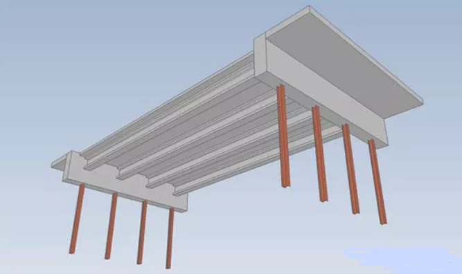
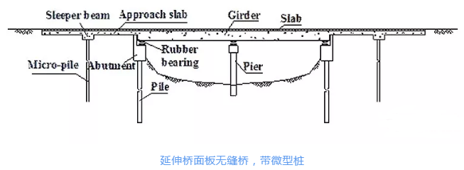
4. Engineers have the ability to design and build various seamless bridges according to local conditions, such as semi-integral seamless bridges and extended deck seamless bridges. In the seamless bridge, Some parts of the bridge support and expansion joints are reserved, but the abutment needs to be specially designed, so that To achieve the seamless effect of the bridge deck. Application limitations of the seamless bridge itself:First, the thermal displacement that the pier and the integral abutment can bear is limited; the prestressed concrete superstructure is 200 The steel structure is within 140 meters; the inclination angle of the bridge deck is less than 45 degrees, and the horizontal curvature is also strictly limited. In addition, jointless bridges require flexible foundations and supports, which cannot be used on soft slope protection, and also have requirements for the environment of pile foundations, and cannot be built on unstable or liquefiable soil etc.
(Source: Road and Bridge Design)
【Copyright Statement】Currently, "Wei Civil Engineers" is a public welfare public account, aiming to provide an online communication platform for civil engineering professionals. The articles pushed by this account are only for learning, communication and sharing for non-profit purposes, and does not represent the views and positions of this official account. All original articles generally "declare originality" according to the service agreement requirements of the WeChat public platform; except for articles whose source cannot be determined, reprinted articles must indicate the author and source. If you feel copyright infringement or other problems, please contact us so that we can delete it in time. If other online media reprints articles from this official account, please also indicate the source! Thank you for your understanding and support! (Wei Civilian)
micro letter Scanscantwodimensional code < span data-raw-text='off' data-textnode-index='12' data-index='399' >offNote'Wei Civil Engineer"
Articles are uploaded by users and are for non-commercial browsing only. Posted by: Lomu, please indicate the source: https://www.daogebangong.com/en/articles/detail/Summary%20of%20Design%20Experience%20of%20Small%20and%20Medium%20Bridges.html
 支付宝扫一扫
评论列表(196条)
测试