
Read the original text and watch the CAD video in the lower left corner
Good lesson recommendation:
13: SU Tutorial: Click to view 14.solidworks tutorial: Click to view
More video tutorials:Click me to view
Tolerance is a concept that is almost only used in the mechanical industry. It is divided into two parts:
Dimensional Tolerance
Shape Tolerance
What is geometric tolerance? The following is taken from Baidu Encyclopedia:
Form and position tolerances are generally also called geometric tolerances, including shape tolerance and position tolerance. Any part is composed of points, lines, and surfaces, and these points, lines, and surfaces are called elements. There are always errors between the actual elements of the parts after machining and the ideal elements, including shape errors and position errors. This kind of error affects the function of mechanical products. The corresponding tolerance should be stipulated during design and marked on the drawing according to the specified standard symbols.
The graphical representation is:
In AutoCAD , there is a special command to create geometric tolerances:TOLERANCE
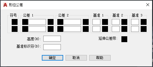
Run TOLERANCE or abbreviated TOL, it will open the dialog box of 【Geometric Tolerance】:< /span>
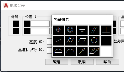
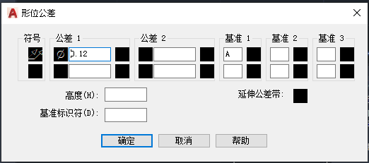
Click on the small square in front of the tolerance 1 , and the symbol of F will appear to indicate the diameter , please be careful not to use %%c in the following input box to display the diameter symbol, in some cases it will not be displayed :
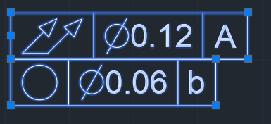
If the tolerance is filled in the second line, a two-line geometric tolerance will be generated at the end:

The name of the object generated in the paper space is【Tolerance】, double-click to return directly [Geometric Tolerance] dialog box to edit.
So far, the explanation of this command is over. However, some users find that when they use it, the column of "Symbols" is full of English letters instead of specific symbols. What should be done in this situation?
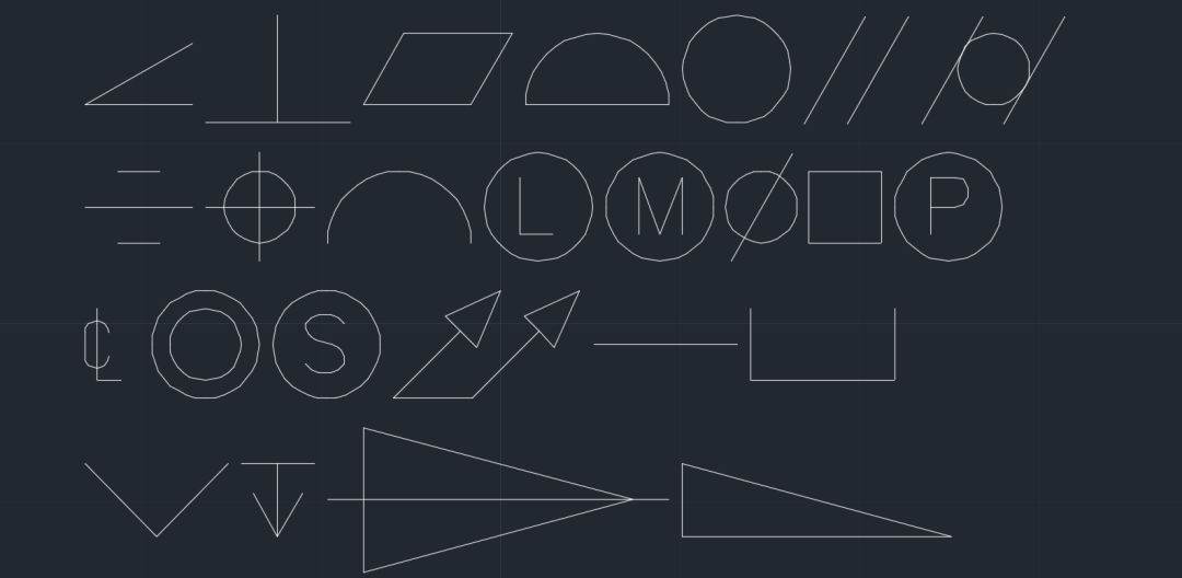
Actually, the symbols in tolerances all come from a set of AutoCAD specific fonts:/strong>gdt.shx The effect of lowercase letters. Now I use this font to write a-z again:
Does it look familiar? There are a lot of symbols we used in geometric tolerances before, and several other symbols such as counterbore, taper hole and drilling depth are very commonly used in mechanical marking. When I reviewed drawings before I often find these symbols, and some designers draw them directly...
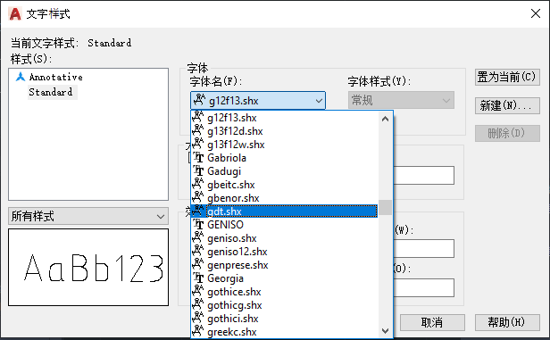
Back to the above question, if you find that the symbols in your geometric tolerance have become letters, don't worry, open STYLE Dialog, look at gdt.shx this font< Does /span> still exist? Is it gone?
It’s okay, justReset AutoCAD It will come back... As for the reason: mainly Because some antivirus software took this font as a virus and killed it...
One MinuteQ&A
Q
AutoCADRandom lines appear in the graph, solve
A
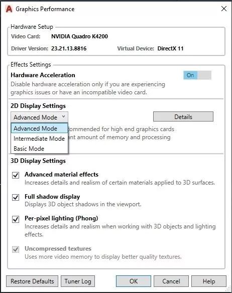
Disables smooth line display. In the command line of AutoCAD, type LINESMOOTHING and set it to off or 0 (zero).
Enter graphicsconfig on the command line, then turn off the smooth line display< /strong>
Note: This article is published with the authorization of Autodesk Vision (id: autodeskvision),Chai Lifeng, click to read the original online Order the latest version of the software.

END
A design sharing site with attitude and materials CAD self-study network WeChat ID: cadzxw Click here to go online to order Autodesk software.
CAD masters are watching


Articles are uploaded by users and are for non-commercial browsing only. Posted by: Lomu, please indicate the source: https://www.daogebangong.com/en/articles/detail/Magical%20gdt%20fonts%20creating%20geometric%20tolerances.html
 支付宝扫一扫
评论列表(196条)
测试