
How to set the national standard of AutoCAD dimension style
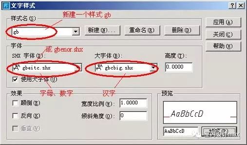
Text style setting: AutoCAD should give priority to *.shx, which is AutoCAD's special font (SHX font), and use less TrueType fonts under Windows (TTF font). The picture below is the text style that conforms to the national standard.
Dimension Style Settings: Step 1 Setting< /strong> public parameters, the second step set the parameters of each sub-style.
Step 1: Settingpublic parameters (1~5)
1. Create a new gb style, and set parameters such as dimension lines and dimension extension lines on the "Straight Lines and Arrows" card, as shown in the figure.
The offset of the starting point in the figure is the standard of the architectural drawing. If it is a mechanical drawing, it can be kept unchanged by default.

2, choose dimension text style

3, consider labeling the scale factor
The scale factor DIMSCALE takes the reciprocal of the scale, such as the output scale is 1:50, DIMSCALE=50; For example, the drawing scale is 1:100, DIMSCALE=100..., this is the case of drawing in the model space. If the layout is used, select "Scale dimension by layout (paper space)", without specifying the value of DIMSCALE.
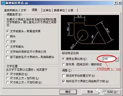
4, the unit can be the default value.

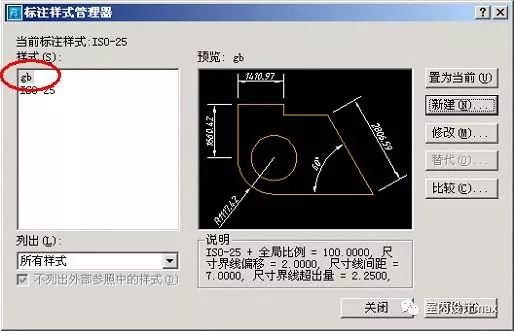
5, public parameter setting is completed, click "OK" to return to the previous dialog box, and you can see the newly created gb style.
Step 2: Set each sub-style (6~14): linear dimension, diameter dimension, radius dimension , angle label
6, SetLinear ruler style
Follow 5, continue to "New", in "Use Under ", select "Linear Dimension".

7, click "Continue" to set parameters for the linear dimension.
For architectural drawings, just modify the arrows to be architectural markers, and change the value of the arrow size to a smaller value. The value here is the horizontal projection length of the slash, and the national standard requires the slash to be 2~3mm long.
All other parameters are set according to the public parameters , if it is a mechanical diagram, the arrow and its size do not need to be changed.

8, click OK to see the sub-style of the linear label under the gb style.

9, set diameter dimension substyle.
Continue to "Create New" in 8, select "Diameter Dimension" under "Used for", click "Continue", and set for the diameter dimension< /span> parameter. First select the text alignment as "ISO standard", so that the diameter dimension can be marked horizontally (this is just a habit).

10, adjust the text and arrow position of the diameter label.

11, click "OK" to complete the diameter dimension sub-style under the gb style.

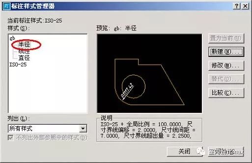
12, the radial dimension substyle is exactly the same as the setting of the diameter dimension.
Note: Even for architectural drawings, arrows are still used for diameter, radius, and angle dimensions. Radial dimension substyles are identical to settings for diameter dimensions.
13, Set Angle dimension substyle.
The national standard for angle marking requires text to be written horizontally.
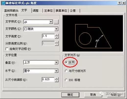
14, OK, the main style setting of the size standard conforming to the national standard is completed, set the gb style as the current style and you're done.
Is it a little troublesome, it doesn’t matter, save the style that set with your own sample middle.
Here are the text details:
The following describes the tabs for dimension style modification:
1. Lines and arrows:
Dimension style is divided into three parts, namely dimension line, extension line and dimension text. These three parts can set their colors separately, and the line widths of label lines and extension lines can also be set separately.
The extension of the label line is the extension of the label line when the arrow style uses a slash line (most commonly used in architecture) Because arrows are generally used in mechanical drawing, some items are invalid.
Marking line is not displayed, and the first half or the second half of the marking line can not be displayed, or not displayed (it can be relatively rare ), this item is mainly for local modification for different annotation objects, and it is generally reserved but not suppressed when setting the annotation type. The extension amount of the extension line and the dimension line is the length of the extension line beyond the dimension line. In mechanical drawing, it is generally set to 2.
Extension lineThe offset from the label point refers to the distance between the starting point of the extension line and the point when specifying the label point, if specified If you set an offset, you will see that the extension line does not start at the label point, but appears outside the label point. Generally this value is 0, then there is no offset.
Second, text
The text refers to the annotation text (called annotation in the previous version), you can choose the text font, color, text height and text position, etc.
Generally, the default standard font is sufficient, because the marked text is the same as the general text, and there is no special requirement.
The text height is generally set to 3.5.
The height of the fractional part is generally used in other unit systems. In the decimal system of mechanical drawing, this item is invalid.
The vertical position of the text is generally the upper side, and it can also be set to the center for angle annotations (the annotation lines are disconnected at this time).
The horizontal position is generally centered, and then adjusted according to the actual situation after marking.
The offset distance from the label line refers to the distance between the bottom of the text and the label line, which is set to 1.
There are three alignment methods for text: horizontal, aligned to callout lines, and ISO standard. The ISO standard means that text is parallel to the dimension line when it is between the extension lines, and horizontal when it is outside the extension lines. "ISO standard" is adopted for radius and diameter dimensioning, while "alignment dimension line" is adopted for other dimensioning.
3. Alignment:
Alignment refers to the way labels are arranged. For the arrangement of text and arrows, it mainly occurs when the labeling distance is too small to accommodate the arrows of the text box between the two extension lines at the same time, and the object first moves outside the extension line. In the options, the first item is generally selected, that is, automatically adjust text and arrows. When using this item, the arrows will always move out of the line first. When you move the text out of the line, if the arrow can be accommodated between the lines, Then the arrow will automatically move inside the line.
The scale of the label content means that items related to size, such as the height of the text and the size of the arrow, are displayed in proportion. Usually "1". There are two fine adjustments:
Manually placing text when marking refers to determining the placement of the text before the end of marking. Generally do not choose.
Always draw dimension lines between extension lines. If not selected, when the arrow is outside the extension line, the dimension line segment between the extension lines will not be drawn. So this item should be checked.
Fourth, the main unit:
In the main unit tab, it is divided into linear dimension (including radius, diameter, coordinates) and angular dimension.
The unit format is the unit system, and for mechanical drawing, the decimal system (Decimal) is used.
The accuracy generally retains two decimal places (ie 0.00), so that inaccurate drawing or inaccurate capture during the drawing process can be reflected from the decimal part of the label.
The decimal point refers to the style of the decimal point, which can be a comma "," or a dot "." In China, it is better to use a dot.
The prefix and suffix are to add some characters before or after the dimension, such as diameter symbol "φ", radius symbol "R" or other words.
V. Conversion unit
The conversion unit is generally not used in mechanical drawing, and the options are roughly the same as those in the main unit. The different explanations are as follows:
The multiples of the main unit are mainly for different units, such as millimeters and meters, and their multiples are 1000, so you can fill in 1000.
You can select the alternate unit to be located below or to the left of the main unit.
Articles are uploaded by users and are for non-commercial browsing only. Posted by: Lomu, please indicate the source: https://www.daogebangong.com/en/articles/detail/How%20to%20set%20the%20national%20standard%20for%20CAD%20dimension%20style.html

 支付宝扫一扫
评论列表(196条)
测试