The previous two issues of basic knowledge text articles have received great response from everyone, indicating that they are still of little use. Next, we will continue to summarize some basic CAD knowledge. Today we will introduce how to insert various symbols and text height issues.
Problem description:
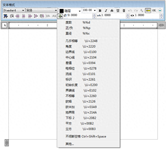
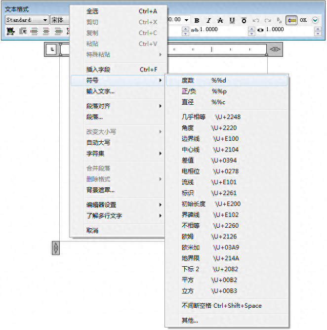
How to insert symbols such as positive and negative, square, cube, diameter, and degrees
Solution
Ø Symbols must be inserted within multiline text.
Ø Open [Text Editor].
Ø Click the [Symbol] button in the [Text Editor], or select [Symbol] in the right-click menu of the text input box.


Problem description:
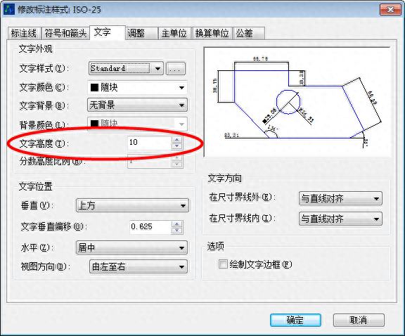
Ø The modification of [Text Height] in the [Text] tab of the annotation style is invalid.
Ø When using the [DTEXT] command, you will not be prompted to enter the text height.

Cause of the problem
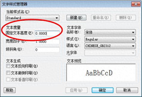
If [Text Height] in the [Font Style] dialog box is greater than "0.0", the height will be automatically set for the text style. Setting it to "0.0" will default to the last text height used.

Solution
Enter the [STYLE] command and adjust the [Text Height] value to "0.0" in the [Font Style] dialog box.
This is the summary of basic knowledge in this issue. If you think it is helpful, you might as well give it a thumbs up. ZW_CAD
Articles are uploaded by users and are for non-commercial browsing only. Posted by: Lomu, please indicate the source: https://www.daogebangong.com/en/articles/detail/CAD-ji-chu-zhi-shi-hui-zong-di-san-qi-ru-he-cha-ru-fu-hao-yi-ji-wen-zi-gao-du-wen-ti.html

 支付宝扫一扫
评论列表(196条)
测试