
Part 1: What is a drawing? Why do drawings need to have scale?
A drawing is a detailed and rigorous instruction, the purpose of which is to summarize and display the results of a single professional work, and provide a basis for collaboration All parties cooperate to achieve a common goal. The characteristic of proportion is produced because of the strictness of the drawings. The following takes the sample drawing as an example to illustrate the meaning of the scale:
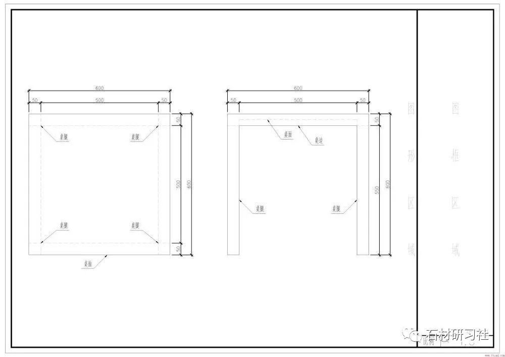

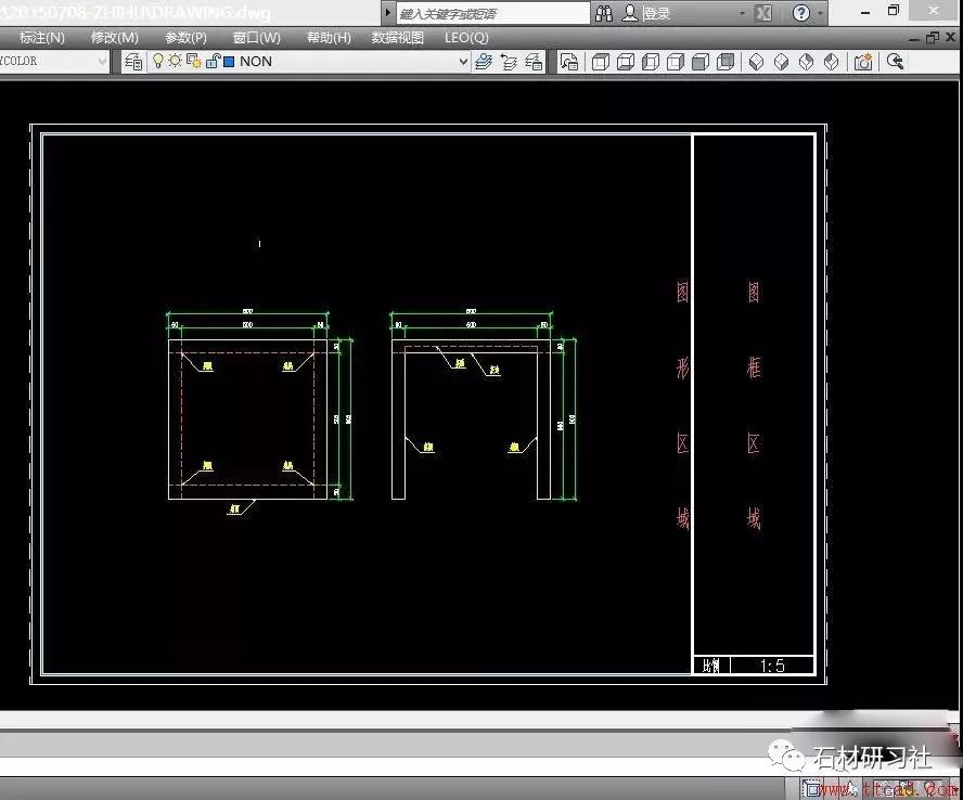
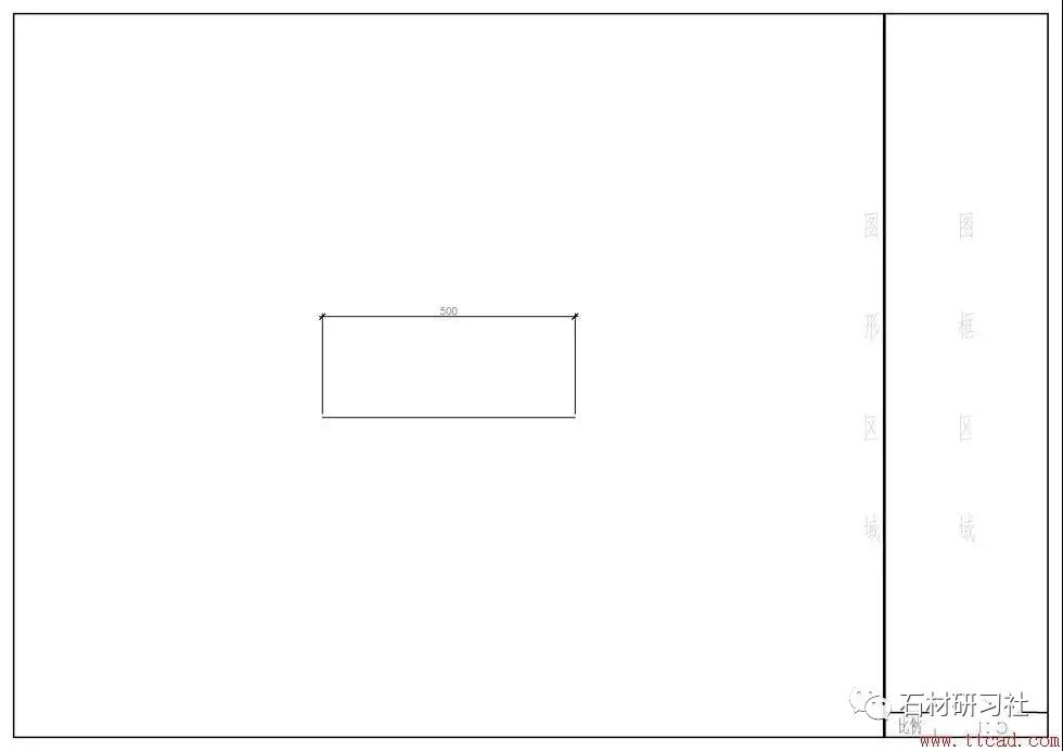
Figure 1 and Figure 2 show the appearance of the same table under different scales of A3 drawings. It can be seen that the scale changes from 1:5 to 1:10 Finally, the size of the table in the figure also becomes 1/2 of its original size. It should be noted that the size of the primitives of the entity class in the figure has changed, but the size of the primitives of the annotation class such as labels and explanatory texts has not changed.
Suppose a furniture maker gets this drawing, without any other face-to-face communication, he can know that we need to make a square table, The length of the table is 600mm, and there are four legs, each of which is 550mm long.
Among them, the square information is obtained from the solid shape line in the figure, and the size is obtained from the number written on the dimension label in the figure, and each thing is separately What function is explained by the explanatory text in the picture, and a rough manual is probably completed.
So, what is the reason we need to draw these figures to scale in a drawing with sufficiently accurate dimensions? The key lies in the solid shape line in the first step. Only in the scaled drawings can we have an intuitive understanding of this object at first glance, for example, it is a square instead of a rectangle, such as the tabletop of this table Compared with its height, the thickness is very small, and there is ample space under the table, which avoids unnecessary workload caused by subconscious misunderstandings.
At the same time, for the purpose of saving paper, we naturally want to put as many solid shapes in a picture as possible, the smaller the font, the better, the proportion Naturally, the bigger the denominator, the better.
However, the recognition ability of the human eye is limited, and too small fonts and graphics are extremely prone to hallucinations and errors when reading, so each The generation of the drawing scale needs to be reasonably allocated according to the size of the drawing and the number of notes, and find a balance between the difficulty of recognition and the amount of information.
Part 2: How to use CAD to draw to scale?
CAD is just a tool to achieve goals faster and improve production efficiency. The method used is not absolutely good or bad, as long as it can meet the needs of users, Then achieve the purpose of this tool, see that there are many solutions in the answer, here we only analyze a few of them:
Scheme A: directly scale the drawing frame in the model
It is a more common practice in domestic design units. According to the previous explanation of "proportion", the so-called "drawing scale" and "frame" proposed by the subject in the title "Scale" does not exist objectively, but is a derivative problem of CAD operation caused by the drawing method of this scheme. "Print scale" is a parameter of CAD when converting graphics to paper. To explain these The ratio must first be understood. The general drawing steps are as follows:
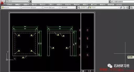
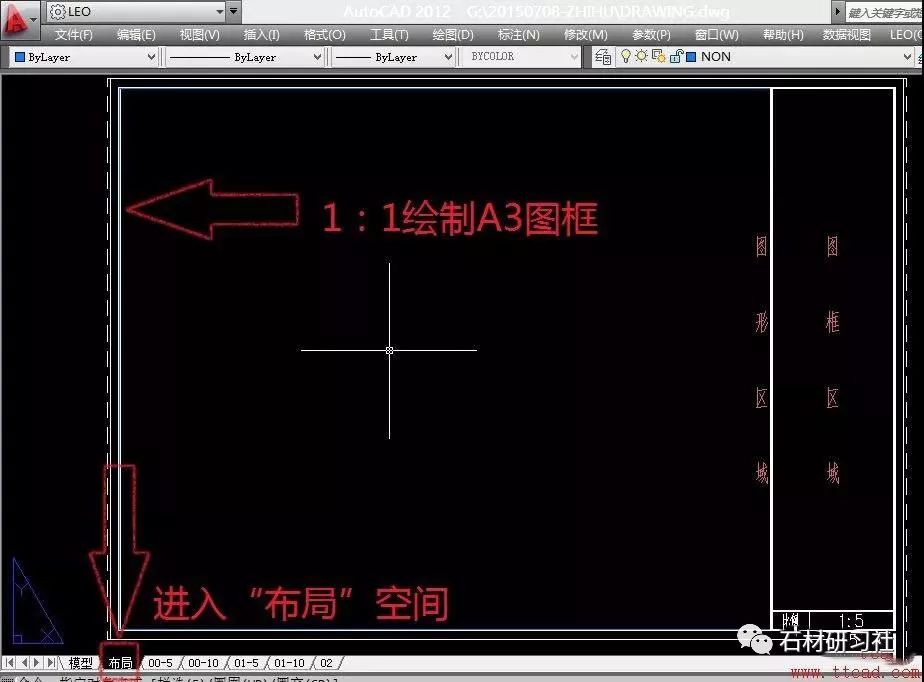
1. Draw graphics according to the so-called "drawing scale":

The "drawing scale" defined here is "the ratio of the length of a line segment in CAD to the actual length of the object it represents", here it is recommended No matter what the drawing ratio is, when drawing the object for the first time, draw strictly according to 1:1.
{Suggestion reason} One advantage of drawing in a 1:1 ratio is that even if the required drawing ratio is not 1:1, the user does not have to draw according to the needs The drawing scale is additionally converted when drawing each line, and can be adjusted as a whole by using the SCALE command after completion;
Another advantage is that when other collaborators open the DWG drawing, they can directly use the "Query" function of CAD to directly query the information of related graphics, such as the length of the line , area, and volume, without additional calculations based on the ratio multiplied by the ratio.
2. Make the picture frame according to 1:1, and then enlarge it by N times (using the SCALE command), until the picture frame can circle the drawn graphics, record it The value of N, then the ratio is the "frame ratio" described by the subject, and the ratio of the frame shown in the sample is 1:5

[Analysis of the reasons for demand generation] From the above two steps, the definition and operation steps of "drawing scale" and "frame scale" can be obtained. The reason for this can be roughly inferred from other answers. First of all, there are a large number of drawings in the design profession that can be drawn in a 1:100 ratio. 100 scale for labeling, and finally put on a 1:100 picture frame, the drawing of the picture and the layout of the picture frame can be completed.
In this case, the drawing scale does not need to be changed in particular. But when a 1:100 graphic suddenly needs to insert a 1:20 detailed drawing, in order to ensure that the whole is still a 1:100 drawing frame, the detailed drawing is enlarged by 5 times ("drawing scale" becomes is 1:5), and the scale of the label is still 1:100. If it is placed in the 1:100 drawing frame, the scale of the detailed drawing is 1:20, so it can meet the requirements of partial drawings in the case of the overall drawing 1:100. It becomes 1:20, and the operation is extremely simple.
3. Define the label and font size according to the determined ratio (that is, the size of the font, the size of the label number, the length of the label line, the size of the label arrow and other proportional parameters) , add the information to be expressed to the drawing. [Refer to the third part for the definition of labeling]
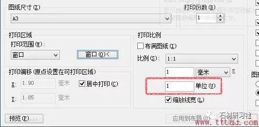
4. Select "File" → "Print" in the menu bar, set the printing parameters according to the following figure, set the printing scale to 5, and set the "Print Range" Select "Window" in the window, select the drawing area, and the obsessive-compulsive disorder patients must fill in the "Centered Printing" option.
"Print scale" can be defined as: a zoom parameter when CAD converts electronic drawings to paper. When you draw a 100mm line, use 1: If you print it out with a printing ratio of 1, then use a ruler to measure the length of this line on paper, and the obtained data will be 100mm; while printing with a printing ratio of 1:10, the measured length will become 10mm.
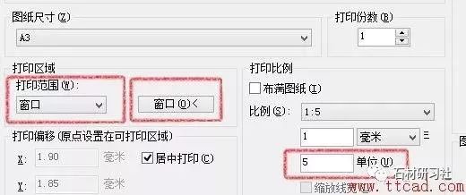
Set print scale related parameters
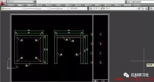
After clicking "Window", select the drawing area
5. After completing the above steps, click "OK" to complete the printing. The printing effect is as shown in the example picture.
Option B: Use the "Layout" function to adjust the drawing scale
At present, the drawing scheme generally adopted by more advanced design firms, this scheme does not have concepts such as "drawing scale" and "picture frame scale", and at the same time the drawing scale The size and the size of annotation primitives are integrated into the concept of "drawing scale" mentioned in the first part. In CAD, it is translated as "annotation scale", which is very easy to understand and operate. It can be used with other CAD functions to issue Yagami continuous skills. advantages, the specific steps are as follows:
1. Also draw graphics at a ratio of 1:1. The graphics refer to the example in Scheme A and will not be repeated here.
2. Click "Layout" to select the graphics card, and draw the frame according to the A3 size 1:1
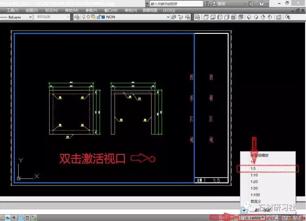
3. Use the "MV" command to draw a viewport in the "graphics area" of the figure to get a full view of the drawing. At this time, the scale of the drawing is a non-integer , need further adjustment.

4. Double-click the viewport area to activate the viewport, click the "Annotation Scale" list in the lower right corner of CAD, and change the "Annotation Scale", such as 1:5. At this time, The drawing scale is the selected "Annotation Scale"
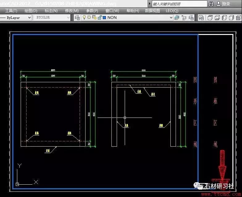
5. Also open the "Print" setting, select the drawing area in the window, but at this time, only need to enter "1" for the "Print Scale".
6. Click "Confirm" to complete the printing, and the output effect is the same as "Figure 1" in this answer
[Part 3] What is the labeling ratio? How to set dimension scale?
First of all, we can simply divide the "marking scale" in CAD into two parts: "marking geometric scale" and "marking numerical scale", "marking geometric scale "That is, after drawing, the size relationship of the label on the paper, such as the size of the font, the length of the end of the line, etc.;
The "label value ratio" refers to whether the label needs to be multiplied by a coefficient to represent the length of the line segment after reading the length of the line segment. After the text part is finished, the following is an example with pictures:

First look at the six line segments in the picture, all of which are 250mm in length, the only difference is the change of the marked scale;
The three labels in the first line, from left to right, the 'label geometric scale' are 1, 2 and 3 respectively, and the value is 250, but the font and The arrows at both ends of the font are bigger than the other;
The three labels in the second line, from left to right, the "label value ratio" is 1, 2 and 3 respectively, although the size has not changed, but The value marked above has changed from 250 to 500 and 750. This part is easier to explain, that is, after the label primitive reads the length value of the line segment "250", it is multiplied by the "label value ratio" 1, 2 and 3. Get the 250, 500 and 750 that you see.
The above is the effect display, and then explain the specific differences of the first line in detail, and then explain how to set these parameters. As a further example:
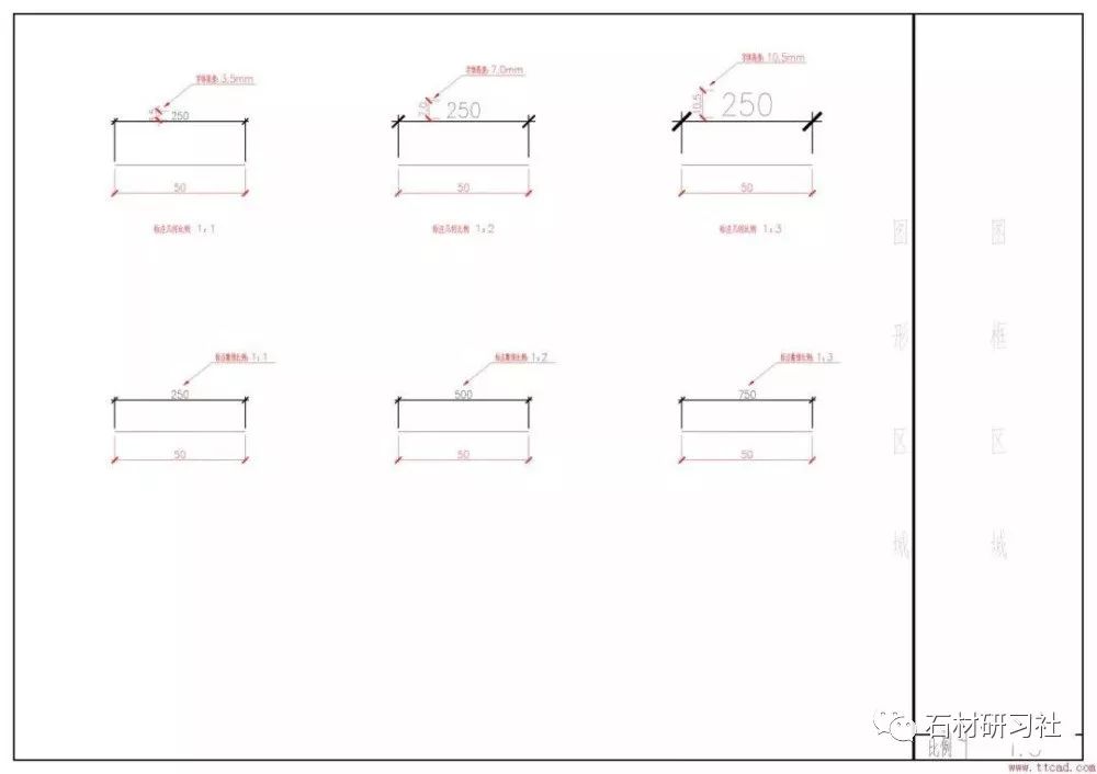
The red part in the above picture is the comment, and the red size is the value measured with a ruler after printing the picture on the A3 drawing. It is not difficult to find that the value in the second line It grows according to the law of 1:2:3. Similarly, the font size of the first line also increases according to the law of 1:2:3, and the arrows at both ends are the same.
How to set?
This is a typical label, first give the definition of each part:
The part of 500 numbers is called "label font"; the line below 500 is called "dimension line"; the thick slash lines at both ends of the dimension line are called "label arrows" ;The two lines perpendicular to the dimension line at the dimension arrow are called "dimension extension lines"; there is a point between the dimension extension line and the marked entity, which is called "dimension start point";
The adjustment of the "geometric ratio" of a label is to adjust the above parameters; the next step is to set the corresponding relationship of the parameters in the label <=>, a picture Must kill! ! !
【Step 1: Tell CAD what dimension you want】
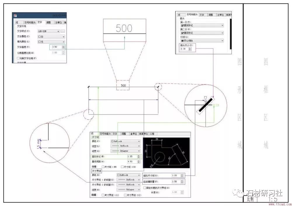
Here is a small science explanation for those who have doubts about the values in the picture. First of all, when filling these values, you only need to consider the one marked after the drawing When you use a ruler to measure the size you want to get on paper, for example, the height of the font is 3.5mm, and the length of the thick slanted line of the arrow is 2.3mm. You don’t need to write a font of 350mm after conversion according to the ratio, because that is After we humans tell the computer our needs, the computer should help humans do what they want. Of course, if the user is used to or likes to do this, it will not affect the drawing effect.
The first step is completed
After completing the first step, you need to tell CAD the corresponding "label geometric scale" and "label numerical scale" for each label pair: for example, One picture kills! ! ! ! !
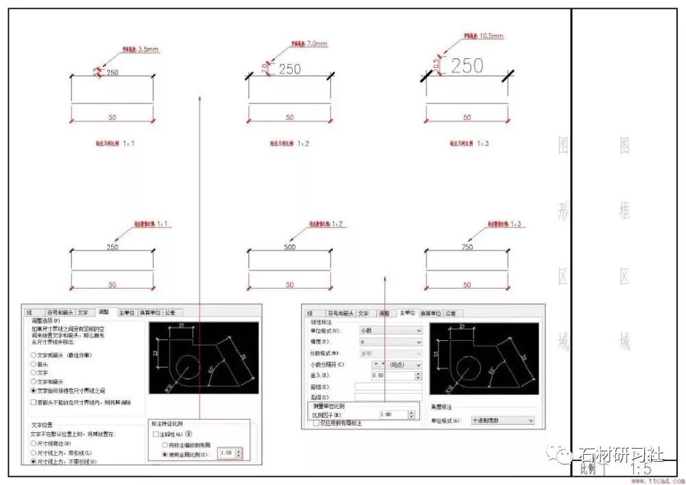
The picture in the lower left corner is "Dimension Geometric Ratio", CAD will automatically multiply the ratio according to the previous text, arrow, and starting point offset length, so as to enlarge the dimension of the dimension of the dimension the goal of.
The picture in the lower right corner is "label value ratio", CAD will automatically multiply the ratio according to the length of the marked element, and then output the result value, the second in the picture The three values in the row clearly demonstrate the effect of this ratio.
For the usage scenario of this ratio, please refer to plan A in the second part, which is to put a 1:20 detailed drawing in a 1:100 drawing frame, due to the drawing scale It has become 1:5, so the "label value scale" of the label scale used in the detailed drawing has changed to 5, so that the value expressed is the exact value we want to express.
Note: From CAD
Hot recommendation
【Stone Research Institute Mini Program】
How to set CAD drawing area! Learn quickly!
The wall CAD node sample and the SU node sample are complete in variety!
Garden road pavement CAD design materials and construction methods
Added a comment function at the bottom of the article, welcome to leave a comment
Contribution. Cooperation. Promotion Please + WeChat 17134996333


Click the picture to understand▵
 Stone Institute
Stone courses around you, stone knowledge and technical article courses.
 Youshi Mall
The exclusive mall for stone people, the designer material selection center.
 Stone industry research
Stone hotspot industry trends decoration design.
Click "Read the original text" to enter Youshi Mall!
↓↓↓↓
Articles are uploaded by users and are for non-commercial browsing only. Posted by: Lomu, please indicate the source: https://www.daogebangong.com/en/articles/detail/A%20detailed%20tutorial%20on%20drawing%20in%20proportion%20to%20CAD%20and%20setting%20the%20dimension%20scale.html
 支付宝扫一扫
评论列表(196条)
测试